Advice needed - changing ST1250 to 9400c but CH doesn't work

From these three checks I got:

9400c/T3 = HW ON = Brown = cable one W07 Red which is connected to WC/T5 (room stat!)

9400c/T4 = CH ON = Blue = cable one W09 Yellow which is connected to WC/T8 (cylinder stat!)

The implication is that the wires I have at 9400c/T3 and 9400c/T4 need to be swapped over.
I agree, though it might be easier to swap WC/T5 and WC/T8.

Doesn't help I can't find a wiring diagram for the ST1250 anywhere on the web.
I can't even find a mention of it on any Honeywell website - UK, USA or Europe. It may look similar to the Horstmann SC7 but that is only a CH control, no HW facility.

In the end I just need to be sure I get 240v from 9400c/T1/T3 and T4 when I need them, and to the right terminals at the WC.
I thought that was the whole object of this exercise. ;)

Note there remain assumptions as to which terminal of the cylinder stat is which because I've not taken it apart in case it won't go back together again!
You can always confirm this at WC end of the cable to the HW stat:

Disconnect the cable at the WC end.
Turn stat to min
Check continuity between all pairs.
The wire which does not have continuity is the CALL (should go to WC/T4)
Turn stat to max
Check continuity again
The wire with no continuity is the SAT (goes to WC/T10)
The third wire is the COMMON (should connect to Programmer HW ON)

So I have one spare wire at the WC that I can't find the other end of, and a similar wire at the 9400c (connected to HW OFF) that I can't find the other end of!!

Still can't find the other end of the wire parked at WC/T6!
If I have got it right, both of these mystery wires are part of the two cables which are linked together behind the plaster, which was done when the old ST1250 timer was moved. I have a horrible feeling that the person who did the move did not bother to crimp these two together behind the plaster as they were not required for the ST1250.

Test 9400c HW OFF produces 240v
I took the wire from 9400c/T3 and connected it to 9400c/T1 and at the other end to WC/T10. I set HW circuit off, CH circuit on and no demand from the cylinder. The grey wire was live with 240v so I assume the HW OFF output works on the 9400c.
To get CH ONLY, you need 240V on the Grey valve wire and 240V on the valve White wire.


Given the time and what I found so far I'm not going behind the fridge yet!
I think you may have to! :(
 
Sponsored Links
From these three checks I got:

9400c/T3 = HW ON = Brown = cable one W07 Red which is connected to WC/T5 (room stat!)

9400c/T4 = CH ON = Blue = cable one W09 Yellow which is connected to WC/T8 (cylinder stat!)

The implication is that the wires I have at 9400c/T3 and 9400c/T4 need to be swapped over.
I agree, though it might be easier to swap WC/T5 and WC/T8.
DONE - was easier at the 9400c in the end - less wires!

Doesn't help I can't find a wiring diagram for the ST1250 anywhere on the web.
I can't even find a mention of it on any Honeywell website - UK, USA or Europe. It may look similar to the Horstmann SC7 but that is only a CH control, no HW facility.
HA! I put the wrong controller - I'd deleted the PDF I downloaded. It's like a Centaur TC7 - looks EXACTLY the same except it's branded Honeywell - functionally the same too but of course no certainty.

In the end I just need to be sure I get 240v from 9400c/T1/T3 and T4 when I need them, and to the right terminals at the WC.
I thought that was the whole object of this exercise. ;)
Yes - I was sort of saying let's face it doesn't matter any more what controller used to be there! :LOL:

Note there remain assumptions as to which terminal of the cylinder stat is which because I've not taken it apart in case it won't go back together again!
You can always confirm this at WC end of the cable to the HW stat:

Disconnect the cable at the WC end.
Turn stat to min
Check continuity between all pairs.
The wire which does not have continuity is the CALL (should go to WC/T4)
Turn stat to max
Check continuity again
The wire with no continuity is the SAT (goes to WC/T10)
The third wire is the COMMON (should connect to Programmer HW ON)
Excellent! Thanks I'll do that

So I have one spare wire at the WC that I can't find the other end of, and a similar wire at the 9400c (connected to HW OFF) that I can't find the other end of!!

Still can't find the other end of the wire parked at WC/T6!
If I have got it right, both of these mystery wires are part of the two cables which are linked together behind the plaster, which was done when the old ST1250 timer was moved. I have a horrible feeling that the person who did the move did not bother to crimp these two together behind the plaster as they were not required for the ST1250.
I agree - or there is a fault with the joint.

Test 9400c HW OFF produces 240v
I took the wire from 9400c/T3 and connected it to 9400c/T1 and at the other end to WC/T10. I set HW circuit off, CH circuit on and no demand from the cylinder. The grey wire was live with 240v so I assume the HW OFF output works on the 9400c.
To get CH ONLY, you need 240V on the Grey valve wire and 240V on the valve White wire.
Yes I know - I'm happy I'm getting the 240v CH & HW calls from the room stat / cylinder stat when they have demand - it was the HW OFF circuit I needed to check this time.


Given the time and what I found so far I'm not going behind the fridge yet!
I think you may have to! :(
You are correct :cry: but I at least I found out that my colleague has a wire/stud detector so at least I don't need to go exploring at random or buy some more kit. Hopefully I'll be checking the crimps tomorrow evening.


Thanks again for your patience and assistance! I now know far more about the workings of my central heating and Y plan wiring layouts than I would have thought possible (ha ha or maybe even thought necessary!).

Colin
 
hi again Colin
Its beginning to look like the problem is going to be the buried crimped joints :cry:

But you do have other options open to you if you dont want to start digging

option 1
run in another cable from the programmer to wiring centre

option 2
use the programmer to do the hot water only and fit a programable stat to do the central heating only

option 3
use the programmer to do the central heating only and fit another time clock in the airing cupboard to do the hot water

option 4
blank off the existing programmer position,connect the cables to provide live and neutral to the wiring centre and put the programmer in the airing cupboard

option 5
convert to s-plan, this involves plumbing,you will have to remove the 3-port ,rework the pipe work and fit two 2-ports

option 6
fit 2 x single pole change over relays adjacent to the wiring centre
(you have no permanent live so you will have to use the white and therefore a second relay but it will work)let me know if you need a diagram

option 7
locate the damaged cable and repair

Matt
 
option 7 - £1

option 1 - £5

option 4 - £20

option 6 - £25+

option 3 - £40

option 2 - £ 75

option 5 - £100+
 
Sponsored Links
option 7 - £1

option 1 - £5

option 4 - £20

option 6 - £25+

option 3 - £40

option 2 - £ 75

option 5 - £100+

option 7 - £1 ......to include for replastering and decorating????, I doubt it

option 1 - £5.......Agreed

option 4 - £20......for a single blank plate and a couple of metres of 5-core and clips? more like £7 ish

option 6 - even 15amp single pole double throw relays are £3.54 from maplins so £7.08 + £3.96 for 2x din rail bases + an enclosure £?......£20 or less

option 3 - he already has a spare time clock, the still working st1250 so price of a couple of metres of 5core/clips (so around £5 or less

option 2 - .........you can get a programmable for around £25

option 5 - £100+......more or less, its definately the most expensive option but i would still say less

mind you these are DIY prices

on another note I think he already probably digging into the utillity wall by now so option 7 it is :D

Matt
 
Hi!
Thanks for the run down of options matt1e, and to D_Hailsham for the view on pricing.

I think the easiest and most desirable solutions in order of preference will be:

Option 7 - The repair
I have reasonable confidence that because two of the three cores at the airing cupboard are crimped through to the programmer that the missing core MUST be buried in the wall; either crimped or made safe.

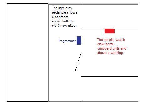
I know when the work was done the electricians had the carpet up in the room above to fit some wiring for cupboard lights at the same time, so depending on how the old cables were routed in the utility room. As I understand the regs they would have to run close and parallel to the ceiling or floor, or pulled up into the rafter space, crimped and run down the kitchen wall side. If they took the wires back up to ceiling level they may have then run them close and parallel down the wall and then through into the kitchen wall - but I doubt this. Also last option would be they crimped the wires at the old programmer site and ran horizontally through to the kitchen wall but this seems out of regs.

Here's the layout:

Have I understood the regs?
More to the point do they seem the likely routes an electrician would consider/take for the rewire? The work was done several years ago so won't be able to confirm the details with anyone.

Regarding the cost of re-decoration etc it will be minimal cost if not in fact £0 additional spend as the work will be behind the fridge freezer. I might need to get some more filler depending on how easily I find the right wires but I'm not going for wholesale destruction! I also have some of the paint left over for that wall so can cover my tracks.

Option 4 - Move the programmer to the airing cupboard.
I hadn't considered this - probably because it's straight forward to do and VERY sensible! :D I think I'll take this option up IF option 7 doesn't bear fruit. Not ideal as we want the programmer where it is, but won't cost more than a short length each of 3C&E and ring-main T&E.

Colin
 
Assuming your electrician followed the regulations (which, unfortunately, many seem to ignore!) then the cable will run within the prescribed safe zones. To summarise, a cable is allowed to run vertically or horizontally in the wall to or from a visible accessory, such as a switch or socket. Cables may also be run horizontally within 150mm of ceiling level, or an internal corner formed by two walls, even without their being any electrical accessories to indicate the cable's presence.

The wiring at the old programmer will hopefully have been pulled back up into the ceiling space - this is generally the most preferable option.

More information on safe zones here.
 
Thanks for the advice.
Haven't done anything these last couple of days, if I get opportunity I'll have a look under the carpet upstairs - hopefully the crimps are there.

Colin

Assuming your electrician followed the regulations (which, unfortunately, many seem to ignore!) then the cable will run within the prescribed safe zones. To summarise, a cable is allowed to run vertically or horizontally in the wall to or from a visible accessory, such as a switch or socket. Cables may also be run horizontally within 150mm of ceiling level, or an internal corner formed by two walls, even without their being any electrical accessories to indicate the cable's presence.

The wiring at the old programmer will hopefully have been pulled back up into the ceiling space - this is generally the most preferable option.

More information on safe zones here.
 
Appears the electrician didn't pull the cables up to the ceiling space as the only wires I found were continuous and I think I know what they were for.

The cables I could see were for the cooker (next to the programmer) and a lighting loop that I traced to a junction box on top of an adjacent cupboard. One other pair of cables that looked to be the ring main feeding the fused switch and that was it.

There's a chance the electrician cut another access point above the site of the old programmer but I doubt it as they would not have been able to move the carpet further back as my son's bunk bed is in the way.


Will post back next week as we've got visitors this weekend and for some reason my wife doesn't consider it a good move to drag the fridge out at this time! ;)

Colin
 
Hi,
Well since our visitors left this afternoon I did some exploration in the walls in the utlity room.

I traced the wires back from the programmer end and found the crimped joints.

One wire had red/black which was routed to 9400c/T1 and 9400c/N respectively via the brown/blue of a T&E cable. I don't know what is at the other end of that cable.

The second was the red/yellow/blue/earth cable as expected - and I found the blue cable cut short - so not a faulty crimp - no crimp at all!

I isolated the brown wire from 9400c/T1 and replaced it with a connection to the blue wire and surprise surprise I can get independent CH now! :D

Sincere thanks to everyone who has helped with this problem!

I'm confident the wiring centre is wired correctly now and there's nothing wrong with the programmer. I can only assume the blue wire wasn't connected at the old site, or I'm sure the electrician would have connected it through to the new site.

Moving forward I was thinking I could do the following:
1. Check the red from the red/black cable doesn't connect to a live.
2. If it doesn't - unmake that joint and replace it with a crimp to the blue wire
3. Make safe the red wire and fill over the inspection hole.

Does anyone have any comments/suggestions about this course of action? I think it all depends what the red/black cable is connected to.

I don't think the red wire will test as live, but I'm wondering where to route it if it does. It runs straight up the wall into the ceiling space (part way along the utility room wall) so I was wondering if it is the original LNE cable for the programmer - this seems unlikely as the fused switch was next to the programmer at the old position -
this cable is nowhere near there and the gauge of cable is too small.

Thanks
Colin
 
One wire had red/black which was routed to 9400c/T1 and 9400c/N respectively via the brown/blue of a T&E cable. I don't know what is at the other end of that cable.

The second was the red/yellow/blue/earth cable as expected - and I found the blue cable cut short - so not a faulty crimp - no crimp at all!
Told you so! :D ;)
D_Hailsham said:
If I have got it right, both of these mystery wires are part of the two cables which are linked together behind the plaster, which was done when the old ST1250 timer was moved. I have a horrible feeling that the person who did the move did not bother to crimp these two together behind the plaster as they were not required for the ST1250.

The other checks/changes you propose seem sensible. Just make sure you know exactly what each wire does, or you may find that the heating goes off when you turn a light on!! :(
 
Funny how the cable issue was the last one I wanted to consider as creating the problem - but then the last thing you check before fixing something is always the thing that needed fixing! :LOL:

I'll check the black/red cable this evening and if all's well isolate the red cable and patch up the wall - didn't create too much mess, and the fridge is back in place covering up the work at the moment so it can't cause concern for my wife either!

Colin

One wire had red/black which was routed to 9400c/T1 and 9400c/N respectively via the brown/blue of a T&E cable. I don't know what is at the other end of that cable.

The second was the red/yellow/blue/earth cable as expected - and I found the blue cable cut short - so not a faulty crimp - no crimp at all!
Told you so! :D ;)
D_Hailsham said:
If I have got it right, both of these mystery wires are part of the two cables which are linked together behind the plaster, which was done when the old ST1250 timer was moved. I have a horrible feeling that the person who did the move did not bother to crimp these two together behind the plaster as they were not required for the ST1250.

The other checks/changes you propose seem sensible. Just make sure you know exactly what each wire does, or you may find that the heating goes off when you turn a light on!! :(
 
Right!
Checked the wire again with everything live and there's no current - it's dead.

So I've broken the joint and made it safe and replaced it with a crimp to the blue wire into the WC and everything's working fine.

Thanks to everyone who posted comments and suggestsions to the thread - much appreciated,

Colin
 

DIYnot Local

Staff member

If you need to find a tradesperson to get your job done, please try our local search below, or if you are doing it yourself you can find suppliers local to you.

Select the supplier or trade you require, enter your location to begin your search.


Are you a trade or supplier? You can create your listing free at DIYnot Local

 
Sponsored Links
Back
Top