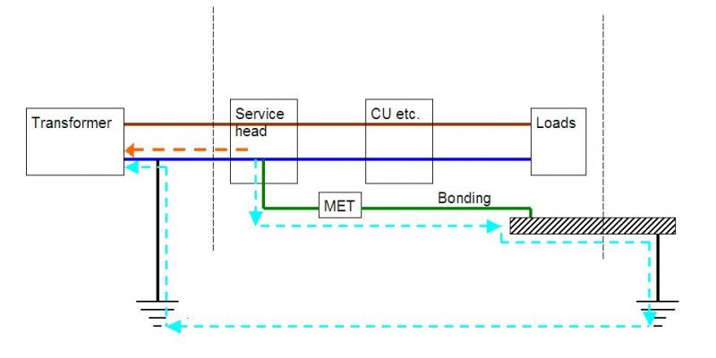
Can anyone clarify what sort of earthing we have.

It also seems to be suggested that on a multi customer PME supply there could be significant currents carried by bonded items even in normal operation.
That is true, but it is also true with a single-customer TN-C-S supply. The path to earth back to the transformer via bonded items is in parallel with the 'proper' route via the supply N/E conductor - the return current to the transformer will therefore be shared between the two paths. If, as can happen, bonded water supply pipes provide a very low impedance path, a substantial proportion of the total 'neutral' current can flow via that route - hence the requirement for larger bonding conductors with TN-C-S installations.
Thanks. You last point is the only one I don't follow. I think I will need to draw it out, and maybe that will make it clear. Or if not maybe you'd comment on my drawing. For the moment I can't see how E and N form a parallel circuit - within my installation N is completely separate from E. The two would join at my end of the supply cable (assuming TNCS). The supply PEN in turn only connects to true earth at one point, at the supply transformer. How does any of my neutral current make it's way off the PEN to seek an alternative route?

Tony S
 
Sponsored Links
The only time I had a instance of earth/neutral wire cut it was due to road works the damage causes was due to voltage and the whole street trying to get it's neutral through a radio amateurs earth mat. All of this would not happen with a single property as it's not a three or split phase supply so loss of neutral means no power.
 
That is true, but it is also true with a single-customer TN-C-S supply. The path to earth back to the transformer via bonded items is in parallel with the 'proper' route via the supply N/E conductor - the return current to the transformer will therefore be shared between the two paths. If, as can happen, bonded water supply pipes provide a very low impedance path, a substantial proportion of the total 'neutral' current can flow via that route - hence the requirement for larger bonding conductors with TN-C-S installations.
Thanks. You last point is the only one I don't follow. I think I will need to draw it out, and maybe that will make it clear. Or if not maybe you'd comment on my drawing. For the moment I can't see how E and N form a parallel circuit - within my installation N is completely separate from E. The two would join at my end of the supply cable (assuming TNCS). The supply PEN in turn only connects to true earth at one point, at the supply transformer. How does any of my neutral current make it's way off the PEN to seek an alternative route?
See diagram - the two dashed lines show the two parallel routes whereby return current can get from the loads in your installation back to the transformer. In my installation, the impedance of the path via bonded pipes is about 0.3Ω - which means that if I had TN-C-S (which I don't) a substantial proportion of the 'neutral' current from my installation would probably try to go via that route.

Does that help?

Kind Regards, John
 
The only time I had a instance of earth/neutral wire cut it was due to road works the damage causes was due to voltage and the whole street trying to get it's neutral through a radio amateurs earth mat. All of this would not happen with a single property as it's not a three or split phase supply so loss of neutral means no power.
As I've just illustrated, if it were TN-C-S you could well have 'some power' if there was a fairly low impedance return path (such as I have) back to the transformer via bonded extraneous-conductive parts.

If you didn't have such a low impedance parallel return path, you might appear to have 'no power' (no current) - but, if you had any load connected to your installation, all of the exposed-conductive parts within your installation would rise to a very high potential relative to true earth - so you'd have to hope that you really had engineered an equipotential zone within your house! Of course, the most obvious reason for not having a low-impedance parallel path would be the absence of main bonding - in which case you really would be at very significant risk (and a risk that an RCD would not protect you against).

Kind Regards, John
 
Sponsored Links
Thanks, the drawing makes it clear, can't believe I couldn't see it without (I hope you didn't have to draw it specially). I'd be pretty amazed if any of our metalwork has that low an impedance back to the transformer via earth, but can't realistically measure it so will have to assume the possibility. I'm really hoping the DNO will confirm TN-S.

Tony S
(ps I wrote this post yesterday, but must have failed to press Submit).
 
Thanks, the drawing makes it clear, can't believe I couldn't see it without (I hope you didn't have to draw it specially).
You're welcome. It didn't take long to 'draw'.
I'd be pretty amazed if any of our metalwork has that low an impedance back to the transformer via earth, but can't realistically measure it so will have to assume the possibility.
If they are just ordinary domestic outhouses, it's very unlikely that they will provide a very low impedance to earth (hence the transformer). It's generally bonded water/gas supply pipes (if metal) that can do that. If you had a clamp meter, you could measure how much current flows in your main bonding cables when you have large loads (e.g. shower+cooker!) switched on to give you some idea.
I'm really hoping the DNO will confirm TN-S
If your property is supplied by split concentric cable, such as you described in your OP, then it almost certainly is TN-S.

Kind Regards, John
 
I found the paperwork for previous electrical work carried out by the former owner shortly before the full rewire which we did. Different electrician, and he's marked it as TN-S.

I also got a reply from the DNO, which is not very helpful. They say I should get a local electrician to check the connection. I suspect my question was misunderstood or otherwise mangled as it was passed on, as they also say that they are installing PME and asked if was interested in being upgraded. I've written back asking what would be involved in his proposed PME "upgrade" and to make sure he is aware that we're served by overhead 11kV to an individual transformer. Also pointed out that electrician's apparently can't tell from the cutout.

I think my question must have been interpreted as asking whether we had a DNO provided earth or not.
 
Hydro Electric engineer came round while I was out, which was a shame, but he dropped a hand-written note through the door identifying our supply as TN-S (which he also called CEW). He did a loop test as well, reporting 0.29, pretty much the same as recorded by the guys who did the rewire.

I think my original question got a bit garbled in their office though, as I had two messages from a lady there, the second one saying that PME is not available at my location, but that my existing earth is within spec and safe.

Tony S
 
Hydro Electric engineer came round while I was out, which was a shame, but he dropped a hand-written note through the door identifying our supply as TN-S (which he also called CEW).
Thanks for the update - that sounds consistent with what you've told us (particularly about the nature of the supply cable). I think 'CEW' stands for 'Continuous Earth Wire' - which I think is old-fashioned-speak for TN-S.

Kind Regards, John
 

DIYnot Local

Staff member

If you need to find a tradesperson to get your job done, please try our local search below, or if you are doing it yourself you can find suppliers local to you.

Select the supplier or trade you require, enter your location to begin your search.


Are you a trade or supplier? You can create your listing free at DIYnot Local

 
Sponsored Links
Back
Top