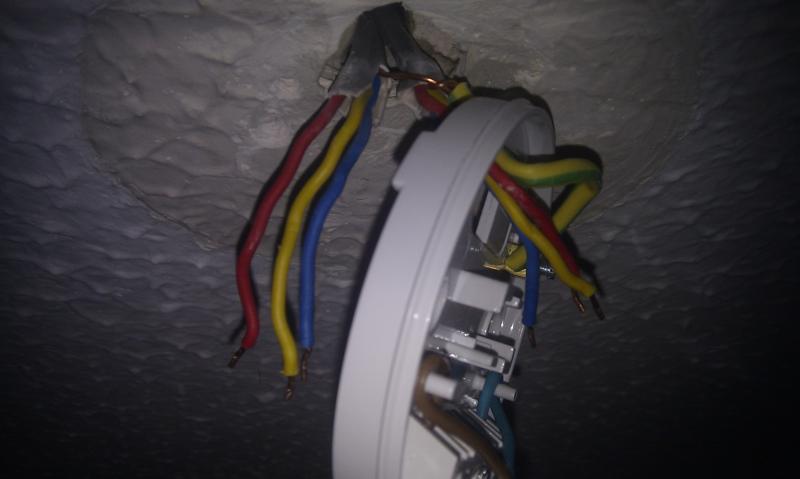
It's hard to see, but this is what I think is going on ...
Ignore the LH switch (RH in the second pic) - that looks like it's just one end of a different 2-way switching circuit.
In the third pic, we can see the blue of one 3C+E in a choc block with a black.
So I think we have red=permanent live, blue=neutral, and yellow=switched live.
Since there are two lights on this circuit, I'm thinking that at the rose :
the two reds should be in the loop terminal, the two blues in the neutral, and the two yellows in the switched live terminal. I'd hazard a guess (can the OP get a photo ?) that in the rose for the other fitting, we are likely to find one or two T+E cables as well - one a feed, possibly a second looping out.
So the arrangement would be - feed to other light rose, link to the rose that's been disconnected (3C+E for permanent live and switched live), dropper to switch (3C+E) including neutral for the circuit controlled by the third switch.
that's just guesswork, and as BAS says, the OP will need to get his meter out and confirm this before wiring up and switching on.
If the OP has has the power back on with these wires out (more than a bit naughty) - does the light controlled by the third switch (the one with two red wires only) fail to work ?


