Earth fault loop impedance test (Ze) with Multimeter?

The point is we have in homes three earthing systems.
TN-C-S as you say switch on an electric fire and measure volt drop.
TN-S only real way is special meter.
TT combination of TN-C-S method plus measure earth rod.

OK TN-C-S measure the volts say 230 and then switch on electric fire 3kW and volts at 225.5 and the loop impedance is 0.35 ohms approx. But control is to take same time and measure voltage without plugging in electric fire and likely same variation.

As to TT well I have never tried to measure with anything but a meter designed for the job. But the first problem is needs to be AC or no current draw or ground will be polarised. Even with the proper meter the problem is getting enough area to put in the test probes.

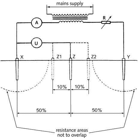
The idea is two test probes are placed a set distance and half that set distance and the half way probe is moved a little closer and a little further away and readings should be the same. If not more distance is required.

I have never tried to work out what it does I am sure some form of Wheatstone Bridge to ensure no current. I would be interested to know who it does work. In real terms only when there is no power do we use that method normal is to use the DNO supply as a reference point.

With either TN system ELI is easy to find it involves a phone call so not worth worrying about but TT is very different. I am sure there is a way to measure with a multi-meter and I am all ears if some one can explain.

This link explains using proper meters but what about with a multi-meter. It is a good question there should be a way.
 
Sponsored Links
As to TT well I have never tried to measure with anything but a meter designed for the job. But the first problem is needs to be AC or no current draw or ground will be polarised. Even with the proper meter the problem is getting enough area to put in the test probes. ... The idea is two test probes are placed a set distance and half that set distance and the half way probe is moved a little closer and a little further away and readings should be the same. If not more distance is required.
I've done it in my time, 'as an exercise', but I wonder how often it is relevant in practice (in relation to an existing installation)? If one measures the EFLI at the origin of a TT installation (with MPB disconnected), using a standard EFLI meter, one will surely have measured true Ze, and the contribution of the DNO's line conductor to that measured total will be negligible, so what one has measured will, to all intents and purposes, be the impedance of the earth electrode (if one wants to know it, as well as Ze), won't it?

Kind Regards, John
 
8.15b.gif

As the picture shows you need an AC source U I assume means volts so V/A = Ω so needs two meters and an AC source also likely something to limit the current that can be drawn.

How much AC is unclear I would assume no more than 12 volt and as such I would expect the current to be quite low just milliamp. The voltage measured would also be very low and clearly it would require two multi-meters not one but yes it can be done.

However this is only a part of the story. One also needs the DNO ELI from memory this is normally considered as 11 ohm. Megger PDF here it gets complex but real point is higher than 1.44 ohm required for a 32A MCB B type so one has to rely on RCD protection. It is normally considered 25 ohm is the upper limit (Megger PDF) so total around 50Ω well within the 200 ohm.

I have worked on a boat where I would not use the ELI tester in case it damaged the diodes and I am sure there are other cases where diodes are put into the earth cable to prevent electrolysis would be interested to hear what others do when there are diodes.

I was rather surprised at the ELI with 55-0-55 volt systems. To trip a B16 MCB will require an ELI of 0.69 ohms and with most small transformers even at the transformer you can't get that figure the internal resistance of the windings is greater than that to start with. So only way would be to use a RCD yet I have not seen a single yellow brick with a RCD built in.

To my mind yellow bricks should be banned but that's another story.
 
As the picture shows you need an AC source U I assume means volts so V/A = Ω so needs two meters and an AC source also likely something to limit the current that can be drawn.
Indeed - as I said, I've done it in my time 'as an exercise' but what about my question as to whether it actually relevant/necessary in relation to an exiting domestic TT installation (i.e. forgetting boats with diodes in the earth path)?
However this is only a part of the story. One also needs the DNO ELI from memory this is normally considered as 11 ohm. ... it gets complex but real point is higher than 1.44 ohm required for a 32A MCB B type so one has to rely on RCD protection.
That's really my point. For a start, I would say that it serious wishful thinking to expect to get a sufficiently low loop impedance for an OPD (rather than an RCD) to give adequate fault protection in a TT installation. However, if one has that hope, as I said, why not simply measure the loop impedance to find out?? Given that, as you say, the impedance at the DNO's rod(s) at t'other end is likely to be at least a few ohms, by the time one has added the resistance/impedance of one's own rod, it would seem next-to-impossible that one would ever get a loop impedance low enough for a B32 (or, come to that, even a B6!) - but if one measured it, one would actually know. How would knowing the resistance of one's own rod help if one already knew what the total loop impedance was (and knew that it was less than 200Ω, or whatever was what one was aiming for, for one's rod alone)? Am I missing something?

Kind Regards, John
 
Sponsored Links
ericmark said:
To my mind yellow bricks should be banned but that's another story.

Hi, can you tell me what you mean by a yellow brick please? I assume that's electrician's slang?
 
... the regs are not happy with L-E fault production 'relying on' an RCD (other than in TT systems).
I cannot see why RCD protection is not acceptable. Unless it is because the modern RCDs are considered to be less reliable than the older designs.
It wouldn't be the first time we'd come across a situation in which we "couldn't see" why the regs are such as they are. I basically agree with you, but I think you may have identified a 'reason' for the regs being as they are. I don't know whether it's necessarily got anything to do with modern RCDs being regarded as any less reliable than older ones, but there is this seemingly fairly widely-held belief that modern RCDs are not all that reliable in-service (we've discussed the {limited amount of} available statistics many times before). Whether they are actually any less reliable than the magnetic parts of MCBs, I just don't know. It could just be that whilst it's easy to test in-service RCDs (and hence identify 'failures') it's essentially impossible to test MCBs - so, for all we know, they could possibly be just as 'unreliable' in service as RCDs.

Given potential uncertainties about the in-service reliability of both RCDs and MCBs, I suppose the one thing to be said for the regs' approach (that one should not rely on an RCD for fault protection, unless that is 'unavoidable') is that it represents 'belt and braces'.
According to some chap called Paul Cook:

In TN systems it is preferable for RCBOs to operate in overcurrent mode when providing indirect shock protection. When they are working in overcurrent mode they are voltage independent, whereas in RCD mode they are not; they need a large enough voltage being applied to drive the circuitry inside. The IEC stipulate that voltage dependent RCDs should operate at voltages as low as 50V, so that the effects of a collapsing voltage in a fault condition are nullified. But if you get an open-circuit neutral, it is possible that an RCBO will not operate in RCD mode with a fault to earth, so the design for a TN system is supposed to ensure that RCBOs operate in overcurrent mode for indirect shock protection, and for this reason the earth fault loop impedence restrictions are the same, and a Type C or D RCBO may not provide a 0.4s disconnection time.

Maybe the concerns about RCBOs also apply to the current generation of RCDs.
 
To my mind yellow bricks should be banned but that's another story.

Why? Disconnection is only important with a reduced low voltage supply for thermal reasons - it is not important to prevent electric shock as the touch voltage will be a maximum of about 30V.
 
The problem with yellow bricks is that they have no over current protection on the secondary side, so a fault can sit arcing away or overloading the typically 1.5mm² extension lead until either the primary OCPD opens, or more typically the thermal cutout opens or the secondary winding of the transformer / extension lead fails which whilst not a real danger in terms of electric shock due to the reduced voltage, it is still a real fire risk.

Remember ohms law. As the line to earth voltage is roughly 4 times lower than a standard mains supply, the fault current is roughly 4 times higher.
 
... Given potential uncertainties about the in-service reliability of both RCDs and MCBs, I suppose the one thing to be said for the regs' approach (that one should not rely on an RCD for fault protection, unless that is 'unavoidable') is that it represents 'belt and braces'.
According to some chap called Paul Cook:
In TN systems it is preferable for RCBOs to operate in overcurrent mode when providing indirect shock protection. When they are working in overcurrent mode they are voltage independent, whereas in RCD mode they are not; they need a large enough voltage being applied to drive the circuitry inside. ....
What on earth does that mean? As things stand (with regs not liking reliance on 'RCDs'), the 'maximum Zs' rules apply (in TN installations) as much to RCBOs as to MCBs, so a negligible impedance L-E fault will result in 'overcurrent tripping' whether it is 'preferable' or not, unless the 'RCD mode' causes the device to operate first.
Maybe the concerns about RCBOs also apply to the current generation of RCDs.
Yes, maybe. This potential problems with RCDs/RCBOs could presumably be avoided by making them 'active' - but that would then have undesirable consequences in the case of power cuts!

Kind Regards, John
 
The transient voltage will not exceed 50 volts if the Ze is less than 1666 ohms.
The RCD will not have any effect on the touch voltage.
When the touch voltage reaches 50 volts the current through the 1666 ohm path to Ground will be 30 mA and this current from Live to Ground and not returning via the Neutral will be sufficient to trip the RCD. Therefor the RCD does limit the touch voltage, the actual limit depending on the impedance of the path to Ground
 
Nearly a year old. But my reference to the yellow brick does refer to the 55 - 0 - 55 volt transformer. An earth fault has just 55 volts so 13A at 230 volts becomes 13x230/55 = 54 amp and 1.5mm² flex can't carry that current. It melts causing a very real fire risk.

However the question was all about measuring the loop impedance to measure impedance one has little option but to use an AC source other wise it would be resistance not impedance.

Years ago the training for measuring made a big thing about ensuring the premises were empty as if there was a fault there was a very real risk should some one touch exposed metal during the test.

The modern meters both test for a very short time and with low current any attempt to measure with a multi-meter and a load would likely be dangerous and with RCD protection near impossible.
 
What on earth does that mean?
Seems pretty clear to me - what is it that you don't understand?
I thought I explained that in the sentence which followed the one you quoted ...

What does he mean by "it is preferable for RCBOs to operate in overcurrent mode" (in response to an L-E fault)? He seems to be implying that one has some (design) choice. As I said, the regs essentially require that (in a TN installation) a circuit is designed and constructed such that a (correctly functioning) RCBO will operate in overcurrent mode in the event of a (negligible impedance) L-E fault (provided the RCD mode does not 'beat it to it'). In the face of such a fault, the presence of RCD functionality (which, in a TN system is essentially there for a totally different reason) is therefore irrelevant, other than as a back-up in case the overcurrent functionality fails. If the RCD functionality did 'beat the overcurrent functionality to it', that would obviously not be a problem.

What, if anything, do you think he is suggesting one can/should do as a result of what he says in 'preferable' (other than omit RCD functionality)?

As you said in your previous post (which is equally applicable when a separate passive RCD is present), I suspect that all he was trying to say is that, in a TN installation, one should not rely on RCD functionality to clear negligible impedance L-E faults - but, as we've been discussing, that's exactly what the regs already say.

Kind Regards, John
 

DIYnot Local

Staff member

If you need to find a tradesperson to get your job done, please try our local search below, or if you are doing it yourself you can find suppliers local to you.

Select the supplier or trade you require, enter your location to begin your search.


Are you a trade or supplier? You can create your listing free at DIYnot Local

 
Sponsored Links
Back
Top