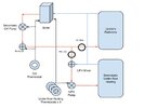
How to wire Nest to both a boiler and a second pump

Yes, to the pump in my diagram. And the black cable next to it is the CH motorised valve

And the black cable on the left to a motorised valve for the hot water. So S Plan it is. Sorry for the confusion.
 
Sponsored Links
The other white cables appear to be a bronze pump for a totally unnecessary secondary return on the hot water and the cylinder thermostat.

That secondary return has been a pain. The bathroom radiators are chrome plated. They all rusted from the inside from being on a freshwater circuit and sprung leaks. I've had to replace them all with stainless.
 
They all rusted from the inside from being on a freshwater circuit and sprung leaks. I've had to replace them all with stainless.

Is that how a secondary return works? I had assumed the fresh cylinder water only went to the taps. But I find them very confusing!
 
Yes, to the pump in my diagram. And the black cable next to it is the CH motorised valve
Thanks,
Are there 1, or 2 black wires in this terminal connection?

Screenshot_20250112_130901_Chrome.jpg


I think I only see one?
If there is one black wire, that connects to and fires the boiler; the connection from the UFH call for heat to the boiler is made elsewhere, and I'm afraid I don't think there's much more we can do for you, unless we can find that connection.
If there are two black wires, it's possible that one is from the UFH.
 
Sponsored Links
Yep, that's a rat's nest all right.
What I would have suggested was doing away with the call for heat from the UFH and taking the CH thermostats call as the power for the UFH zones and pump. Depending on how it's wired though this may cause the ufh thermostats to lose power until the CH thermostat calls for heat which is less than ideal and would require further wiring mods. Would also mean that the UFH could only run while the radiators were calling for heat.
Really what you want is an extra zone valve and repositioning of existing central heating valve.
 

Attachments

  • UFH Heating .jpg
    UFH Heating .jpg
    72.8 KB · Views: 5
Is that how a secondary return works? I had assumed the fresh cylinder water only went to the taps. But I find them very confusing!

Maybe in a more competently built house. I met the plumber who did mine (after it was completed) and he was very proud that he'd thought to plumb the towel rails into the secondary return so they would come on with the HW circuit instead of the CH. Not realising that the towel rail's he'd installed needed inhibitor.
 
Are there 1, or 2 black wires in this terminal connection?

Folks, this is awesome. I've been trying to get a grip on this problem for literally 15 years.

There are two black wires.

PXL_20250112_151506255.jpg


So, are you saying that those two black wires are the call for heat from the UFH and the CH thermostat?

If so, we're close to the key to my problem

+ The CH thermostat fires the motorised valve and the secondary pump when it calls for heat.
+ The UFH only fires the boiler, not the CH valve or the secondary pump

If the UFH calling for heat did everything the thermostat did, then that would solve the issue that my UFH doesn't get flow unless the whole house is cold. That would make the smart device question much easier (and I might not need them at all).
 
Would also mean that the UFH could only run while the radiators were calling for heat.
Really what you want is an extra zone valve and repositioning of existing central heating valve.

Yes, that's what I have now. The UFH doesn't get flow unless the CH thermostat calls for heat.

I think you diagram is how it was supposed to be installed. There is a UFH valve where you drew it - I missed that off my diagram.

There is one radiator (in the 4th bedroom) that is hot whenever the boiler is running, regardless of any thermostat or valve. I'm assuming that those pipes were where the UFH was supposed to be connected, as a third circuit. But somebody connected the UFH to the 4th bedroom radiator pipes and vice versa.
 
UFH wiring centre, I take it 3 cables on the right are the 3 zone valves, where are the 2 on the left going?
 
So, are you saying that those two black wires are the call for heat from the UFH and the CH thermostat?
Not quite. When either of the two zone valves are active and in position, a switched live is sent down the orange wires.
One of the black wires that is connected to the orange wires in that terminal block will fire the boiler.
We don't know what the other black wire does, especially given the complexity of your system - it could be another pump connection for example.
But given your description of the UFH - it fires the boiler, but doesn't power the valve - a switched live from the UFH wiring centre is getting to the boiler somehow, and this may possibly be the place.

Assuming you haven't got a multimeter and you feel like experimenting; we could attempt to disconnect one of the black wires (with power safely isolated), and temporarily connect it to a spare unused terminal in the wiring centre.
If the boiler doesn't fire when the rad heating is called for, the disconnected wire goes to the boiler. Swap the wires back around.
If the boiler does fire when rad heating is called for, turn off the rad thermostat and see if the UFH thermostat still starts the boiler. If it does, then the UFH connection is somewhere else and put both black wires back in their original position.

Only attempt this if you are confident you understand what I'm trying to suggest! :)
 
Maybe in a more competently built house. I met the plumber who did mine (after it was completed) and he was very proud that he'd thought to plumb the towel rails into the secondary return so they would come on with the HW circuit instead of the CH. Not realising that the towel rail's he'd installed needed inhibitor.
But the towel rails cant be coming on with the DHW circuit, they will only come on when a HW tap is opened. If they were on the DHW circuit they would have inhibitor.
 
UFH wiring centre, I take it 3 cables on the right are the 3 zone valves, where are the 2 on the left going?
I'd assumed that one powered the UFH valve/pump, and the other went to the boiler (not the wiring centre we're discussing with RandomGrinch). But I'm hoping that it might go through the wiring centre. Watch this space.
 
Assuming you haven't got a multimeter and you feel like experimenting; we could attempt to disconnect one of the black wires (with power safely isolated), and temporarily connect it to a spare unused terminal in the wiring centre.
Yes, I have a multimeter and I'm not afraid to use it. Hold my coffee.
 
Last edited:
But the towel rails cant be coming on with the DHW circuit, they will only come on when a HW tap is opened. If they were on the DHW circuit they would have inhibitor.
It's a secondary return so the bronze pump returns DHW to the tank so you always have hot water at the tap.
 
But the towel rails cant be coming on with the DHW circuit, they will only come on when a HW tap is opened. If they were on the DHW circuit they would have inhibitor.
We're off-=topic now, but my DHW circuit is actually a circuit with it's own pump (not gravity fed). The secondary return pump (a special bronze one that doesn't corrode in fresh water) circulates hot water around the circuit so there's instant hot water when you run a tap. Towel rails on on that circuit.
 

DIYnot Local

Staff member

If you need to find a tradesperson to get your job done, please try our local search below, or if you are doing it yourself you can find suppliers local to you.

Select the supplier or trade you require, enter your location to begin your search.


Are you a trade or supplier? You can create your listing free at DIYnot Local

 
Sponsored Links
Back
Top