Level 3 C&G cable sizing calculations

Joined
29 Jan 2012
Messages
70
Reaction score
2
Location
Dorset
Country
United Kingdom
Just started Level 3 C&G and we're doing cable sizing calcs. Using a previous years exam question.

We ran through a few examples of radial circuits, all well and good. Following this proceedure:

Work out total load on circuit from plan.
Work out design current. Ib.
Ib<In<It
Find suitable breaker that's bigger than the Ib.
Now find It, tabluated current, by using cable factors Ca, Ci, Cf and Cg.
Once we have It, look up the size of cable for the given reference method of installation, in this case, Single Phase multicore, Method B. using table F5i in the On Site Guide.
Finally, look up volts drop for the selected cable CSA and make sure its less that the allowable limits.

All well and good with the radial examples.

Then we come to a ring final power circuit. We're told that the design current is 23A and so a 32A breaker is to be used.
Applying cable factors totalling 0.8 we get an It of 40A.

If we look up 40A in table F5i in the OSG, we find that we need 10mm2 cable! How can this be right? Everyone uses 2.5mm2 and I would doubt that you could fit two10mm2 tails into a 13A socket terminal!

Even the lecturer was confused by this.

I assume that as the circuit is a ring, the current is halved somewhere in the calcs or is a ring circuit just an oddball requiring a different calc?

Any I going mad or missing something here? Any help most welcome!
 
Sponsored Links
Well, 6mm² has a CCC of 47A so not sure why you say 10mm².

The ring circuit was devised with BS3036 30A fuses in mind and the regulations are still written for them. They might be designed a bit more leniently for MCBs but they are not.

Anyway a ring circuit is like two 2.5mm² in parallel so could have a CCC of 2x 27A, i.e. 5mm² and 54A but because of the danger of one end of the ring taking too much of the shared load the circuit is limited to 54 x 60%, i.e. 32.4A.

The OSG is not a very good publication and why are you using method B?
Use Table 4D5 in BS7671 which is for flat T&E and doesn't give method B.
You should be referencing half of the 40A, i.e. the 20A min CCC of a ring circuit conductor as per the regulation 433.1.204.
 
Last edited:
Then we come to a ring final power circuit. We're told that the design current is 23A and so a 32A breaker is to be used.
Applying cable factors totalling 0.8 we get an It of 40A.
Firstly: why 0.8?

Then assuming that needs doing, aren't you doing it the wrong way round?
 
Sponsored Links
Well, 6mm² has a CCC of 47A so not sure why you say 10mm².

The ring circuit was devised with BS3036 30A fuses in mind and the regulations are still written for them. They might be designed a bit more leniently for MCBs but they are not.

Anyway a ring circuit is like two 2.5mm² in parallel so could have a CCC of 2x 27A, i.e. 5mm² and 54A but because of the danger of one end of the ring taking too much of the shared load the circuit is limited to 54 x 60%, i.e. 32.4A.

The OSG is not a very good publication and why are you using method B?
Use Table 4D5 in BS7671 which is for flat T&E and doesn't give method B.
You should be referencing half of the 40A, i.e. the 20A min CCC of a ring circuit conductor as per the regulation 433.1.204.
Thanks for responding!

The question specified 0.8 for the grouping cable factor Cg, 1.0 for the temp factor Ca. 1.0 for Cf. No other factors needed.

It also specified method B. The example is t&e in dado trunking.

We were told to reference tables F5i and F5ii. Table F6 being for other installation methods.

So with an It of 40A, table F5i shows column 4, 1 two core cable, single phase method B, 6mm has a limit of 38A. 10mm for 52A.

I assumed that the ring circuit would split current so it halves somewhere in the equation.

I also read the regs book section of ring circuits specifying 2.5mm and of course that's what anyone would use, however this is an exam question indended, I assume, to show that the candidate knows how to run through the process above!
 
The question specified 0.8 for the grouping cable factor Cg, 1.0 for the temp factor Ca. 1.0 for Cf. No other factors needed.
It also specified method B. The example is t&e in dado trunking.
Ok, so just a mathematical exercise very unlikely to be the case in real domestic situations.

Therefore there can be no actual explanations of any odd results that ensue.

We were told to reference tables F5i and F5ii. Table F6 being for other installation methods.
Ok.

So with an It of 40A, table F5i shows column 4, 1 two core cable, single phase method B, 6mm has a limit of 38A. 10mm for 52A.
Maybe, but there are two cables and the OPD is a 32A device so it doesn't matter.

I assumed that the ring circuit would split current so it halves somewhere in the equation.
It does - not exactly halved - but that doesn't affect the calculations.

I also read the regs book section of ring circuits specifying 2.5mm and of course that's what anyone would use, however this is an exam question indended, I assume, to show that the candidate knows how to run through the process above!
Very likely but it is not fair to use implausible criteria.

Perhaps you are supposed to do the radial calculations and then point out that such figures cannot apply to ring circuits - but don't take my word for it.


Then we come to a ring final power circuit. We're told that the design current is 23A and so a 32A breaker is to be used.
Applying cable factors totalling 0.8 we get an It of 40A.
Shouldn't you just correct the 20A figure (min.CCC for ring conductors) and divide by 0.8 - 20A/0.8 = 25A - so still alright.

You can't do it so that it results in a higher rated OPD.
 
Then we come to a ring final power circuit. We're told that the design current is 23A and so a 32A breaker is to be used.
Applying cable factors totalling 0.8 we get an It of 40A.

or is a ring circuit just an oddball requiring a different calc?

Building on what ELFI said and hopefully not repeating him too much....

Yes, a ring final is a special case, if you have a look at 433.1.204, you'll see that a ring is (subject to following the normal rules for a ring) is deemed to meet the requirements od 433.1.1 provided its on a 32A and the current carrying capacity of the cable is not less than 20A

If you just go back to your A2 radial socket outlet circuit for a moment, thats on a 32A device and as such the cable needs to have a current carrying capacity of at least 32A so you are appling your correction factors to 32A when selecting your cable, of course, needing 10mm for that cirucit is still an issue, but we will set that asside for now.

If you still needed to base on 32A, there would be no point at all in rings (some folk would say thats the case anyhow, but we will not go there), but we know that we need to make sure the cable used can carry at least 20A because of 433.1.204 so we use that as the figure before we start with the correction factors. So 20/0.8 = 25A. Now 2.5mm 6242Y is good for 27A clipped direct if I remember correctly.

As a side point, I'm pretty sure instead of a rigid 32A/20A it used to just be set at 2/3 of the protective device rating and while that would have perhaps allowed 4mm/40A rings, anything other than a 32A circuit was practically unheard of. It got changed when we adopted protective devices based on the Renard series of perfered numbers to align standards with eurpeon ones. 2/3 of 32A is a bit more than 20A and I think they found it could cause issues with some installation methods commonly not compling with 2.5 even when no other factors were in play. So I think they commisioned some lab tests and looked at the data that came back and decided that it the rule could now be 32MCB / 20A Cable, and they inserted a new table, 4D5, specifically for twin and earth into the regs book.
 
Thanks guys.

I'm still not sure what C&G are getting at, slipping a ring circuit into the question, which is a set of 7 circuits, all radial except one.

It's in the form of a grid sheet.

The fact that each circuit in the grid has the same sections for filling in the Ib, In, It, CSA etc etc suggests that the 'correct' answer for the ring circuit isn't to just quote the Regs Book on rings and ignore the grid for the that circuit., but rather fill out all the boxes and end up with the bonkers answer... It woulldn't be the first time C&G have bonkers 'right' answers in exams!

It's just a bit annoying as we're being taught the method to use for the radial circuits but not the 'other' rule for rings thats in the Regs book, which we all know is what we do in the real world (2.5mm2 ring wiring on a 32A breaker). As I said, the lecturer was none the wiser when the calcs came out at 10mm2 required and couldn't explain why its not correct.

I've yet to find a passage on use of 2.5mm2 for ring final circuits in the OSG that says what it says in the Regs Book, but I'll have another flip through.

I'm back in class tomorrow so I'll see if we can get some sort of conclusion to it...

(Yes, going with 20A does fit with 2.5mm2 according to table F5i, it's good for 23A, ref method B, Adam!)
 
Last edited:
Just found that the OSG does have appendix H for Household and similar installations, which shows 2.5mm2 for a ring.

However this example question is not a house, its a shop. A PC shop and the ring circuit is in the repair room.

No idea if that has any bearing on the matter though!
 
However this example question is not a house, its a shop. A PC shop and the ring circuit is in the repair room.

No idea if that has any bearing on the matter though!

Not really in terms of loading, generally the load is going to be low in that situation, you do have to watch that you have sockets spaced sensibly around the room, so if you have a dado drop in the corner and then dado trunking around two walls, you don't go through all the sockets with one leg and then have the other returning all the way back. You take one leg through sockets 1,3,5,7 etc and the other through 2,4,6,8.

These days with it being on RCD you want to limit the amount of earth leakage to prevent nuisence tripping, you want to aim for no more than about 8 desktop pc setups per 30mA RCD.

Even though you are trying to minimise earth leakage per circuit, its possible that you could see 10mA ish per circuit, so ideally you would want to impliment high inetgrity earthing, a ring is highly suited for it. You just make sure you terminate the earths at separate terminals in the sockets, and at the board, you identify the conductors with cable markers and make sure that each ring has its earths in separate terminals, you can either pair the rings, so if you had rings A and B, you could have a,b in one earth terminal and a,b in the next. Then the same with c,d etc. Or stagger them. a in first terminal, then a,b. next one b,c. after that c,d etc. As long as all conductors are clealy identified (as they arn't identified by what terminal position they are in) and no ring that requires H/I/E as its earths in the same terminal as each other, you can do it how you want (within reason, complete randomness would probably make the next guy question your sanity....)
 
Many years ago I wrote an excel sheet to work it out, the problem is the mV/A/m needs correcting, so ring final comes out something like
1727398046582.png

My problem was it was so complex, it was simply too easy to make an error. So only way was to make a program so I could not miss read my slide rule.

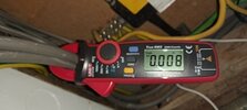
As to leakage I have see it said 30% is the limit for back ground limit, so 9 mA, but until last year no way to measure it, got my new clamp on. Diffrence line neutral 8 Feb 24 reduced.jpg So yes I can measure it, but as to the capacitive and inductive leakage per meter of twin and earth, never seen any figures, I suspect something like 300 Ω ribbon cable, I remember doing it for my RAE and degree, but could not remember how it was done now.

Phrases like correctly terminated comes to mind, and use of balums, etc. But even with radio never really worked it out, used the VSWR meter to measure, and would adjust a variable capacitor to get as close as we could.

I do not remember doing it at level 3, it was level 5 before we had to work that out, still don't know how I passed.

Mind you when I did level 3 we were still using steam tables, and slide rules.
 
Just found that the OSG does have appendix H for Household and similar installations,
I see the title of Appendix H is "Standard Circuit Arrangements for Household and Similar Installations".

which shows 2.5mm2 for a ring.
Well, it would.

Apart from MICC, that is the minimum CSA allowed for the UK ring final circuit even though 1.5mm² T&E method C has a CCC of the required 20A; a consequence of still catering for a BS3036 30A fuse.

Any derating of the cable CCC because of installation methods would result in the use of larger cable for the affected area; not the whole circuit. Of course, the never mentioned option is - do not install the cable in such areas.
(Yes, I know this was just a course question so I do not know what the compilers were hoping to achieve)

However this example question is not a house, its a shop. A PC shop and the ring circuit is in the repair room.
No idea if that has any bearing on the matter though!
As a ring circuit for sockets can only be designed complying with 433.1.204, I wouldn't think being a shop can make any difference.


I feel your initial query is simply because of the error of stating that because of a 0.8 derating factor the It becomes 40A from a design current of 23A - which itself is a silly thing to say about a ring circuit.
 
Well another week passed and I still don't have a proper answer to where the process is wrong. To reiterate, this is not a question for a real life situation, its a C&G test question.

I fully understand that 2.5mm2 is the norm for Ring Final and that the regs book says that as long as there a 32A breaker, you need a 20A capacity cable, 2.5mm2.

The issue is that we're going through the design grids for lighting and radial circuits, following the Id<In<It rule and taking into account the derating factors. This all works great for radials and lights but makes no sense for Ring Final.

The lecturer can't figure it out either.

Oddly the 'correct' C&G answer to the question (what size cable for a ring final with a 32A breaker) is 4mm2 but I have no idea why.
 
RFCs are a kluge, they are "deemed" to be compliant cos the regs say they are.
 
As well as that, as I pointed out, the regulation is written for a BS3036 30A fuse so the cable has to be derated by the 0.725 factor.
27 x 0.725 = 19.575.

Therefore, it is not really possible to match values to a 32A MCB with the mandatory things you must do.

Well another week passed and I still don't have a proper answer to where the process is wrong. To reiterate, this is not a question for a real life situation, its a C&G test question.

I fully understand that 2.5mm2 is the norm for Ring Final and that the regs book says that as long as there a 32A breaker, you need a 20A capacity cable, 2.5mm2.
Yes, but it does not allow you to use a 20A cable (except MICC); you must use a 27A 2.5mm² T&E.

The issue is that we're going through the design grids for lighting and radial circuits, following the Id<In<It rule and taking into account the derating factors. This all works great for radials and lights but makes no sense for Ring Final.
Obviously it cannot. See above.

The lecturer can't figure it out either.

Oddly the 'correct' C&G answer to the question (what size cable for a ring final with a 32A breaker) is 4mm2 but I have no idea why.
That is not the correct answer.

Using 4mm² cable it would not need to be a ring final; it could be a radial; therefore the question is invalid.

433.1.204 Accessories to BS 1363 may be supplied through a ring final circuit, with or without unfused spurs,
protected by a 30 A or 32 A protective device complying with BS 88 series, BS 3036, BS EN 60898, BS EN 60947-2
or BS EN 61009-1 (RCBO). The circuit shall be wired with copper conductors having line and neutral conductors
with a minimum cross-sectional area of 2.5 mm2
except for two-core mineral insulated cables complying with
BS EN 60702-1, for which the minimum cross-sectional area is 1.5 mm2. Such circuits are deemed to meet the
requirements of Regulation 433.1.1 if the current-carrying capacity (Iz) of the cable is not less than 20 A and if,
under the intended conditions of use, the load current in any part of the circuit is unlikely to exceed for long periods
the current-carrying capacity (Iz) of the cable.


No sums necessary.
 

DIYnot Local

Staff member

If you need to find a tradesperson to get your job done, please try our local search below, or if you are doing it yourself you can find suppliers local to you.

Select the supplier or trade you require, enter your location to begin your search.


Are you a trade or supplier? You can create your listing free at DIYnot Local

 
Sponsored Links
Back
Top