

Hi all,
I’m looking for some help with some light switch wiring at my parents. Dad replaced a switch and can’t get it working correctly.
Setup is as follows.
3 gang switch in the downstairs hallway. Single gang switch on the landing upstairs.
The hallway switch controls an outside light, the hallway light and the landing light.
The problem is the landing light isn’t working as expected. The landing light must be in the on position for the hall switch to work.
E.g with the landing switch set to on, the switch in the hall turns the landing light on and off.
Parents go to bed and turn off the landing switch. The landing light goes off as expected but the switch in the hall no longer controls the landing light at all.
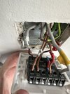
I’ve attached a pic of the current wiring. He labelled these himself with some tape prior to changing the switch but must have made an error as it’s not right.
Something simple I’m sure so any help much appreciated.
I’m looking for some help with some light switch wiring at my parents. Dad replaced a switch and can’t get it working correctly.
Setup is as follows.
3 gang switch in the downstairs hallway. Single gang switch on the landing upstairs.
The hallway switch controls an outside light, the hallway light and the landing light.
The problem is the landing light isn’t working as expected. The landing light must be in the on position for the hall switch to work.
E.g with the landing switch set to on, the switch in the hall turns the landing light on and off.
Parents go to bed and turn off the landing switch. The landing light goes off as expected but the switch in the hall no longer controls the landing light at all.
I’ve attached a pic of the current wiring. He labelled these himself with some tape prior to changing the switch but must have made an error as it’s not right.
Something simple I’m sure so any help much appreciated.
Attachments
Last edited:


