Open vented system, No HW or CH, BAXI 80HE boiler shows Ignition Lockout after tried to start a few times

Looks like something is blocking the flow when in HW only and actually when in the loft doing the manual spindle switch to HW only (programmer on HW only too) I observed the gurgling and pipe wobble until I bled the vent by the coil. It was 14W that went up to 16W after bleeding.

Could the HW circuit be blocked somehow by sludge or air is getting in somehow as I need to bleed it. When I did the retest of HW only with the actuator head on I did not see this 14W pump operation as it was 18W.
 
Sponsored Links
Can't remember, have you got a sealed of open vented system??.
If you are running with HW&CH and change over to HW only does the boiler stay firing or stop briefly while changing over and then fires up and continues to run continuously?.
What is the boiler setpoint temp and the normal cylinder SP temperature.
What is the max and min output of your boiler
Can you post a photo of this vent?,
 
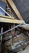
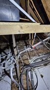
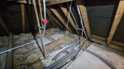
I see you have a OV. system, how is the vent and cold feed done, are they on the boiler flow where from the boiler you gave vent then cold feed then pump?

Can you get someone to sart the boiler on HW only and see if you get some vent pump over and check it again when boiler is switched off, you may have to wait for 3 mins or so before the circ pump stops.
 
Open vented system AFAIK.

I will have to do the HW&CH to HW test and report back. I think the setting before I boxed it up was that it was just CH on as the last test of manual spindle changes.

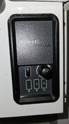
The boiler SP (if you mean the temperature gauge - attached) on the boiler is currently set to HIGH (max setting). The normal cylinder SP is 60C.
Max and min output of the boiler for 80HE Plus heat only boiler according to online manual are:
MAX - 22.00kW, 75,000 Btu/hr
MIN - 9.14kW, 31,180 Btu/hr

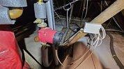
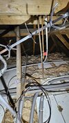
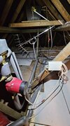
See the vent photo attached with the F&E tank in the background.
 

Attachments

  • photo 1.jpeg
    photo 1.jpeg
    304.8 KB · Views: 25
  • WhatsApp Image 2024-10-22 at 13.33.40.jpeg
    WhatsApp Image 2024-10-22 at 13.33.40.jpeg
    278.9 KB · Views: 23
Sponsored Links
I see you have a OV. system, how is the vent and cold feed done, are they on the boiler flow where from the boiler you gave vent then cold feed then pump?

Can you get someone to sart the boiler on HW only and see if you get some vent pump over and check it again when boiler is switched off, you may have to wait for 3 mins or so before the circ pump stops.
The test here you mean expansion of water discharged through vent pipe into the F&E tank?
 
The test here you mean expansion of water discharged through vent pipe into the F&E tank?
Yes, just watch for any spurt of water from it when the circ pump starts and stops.
Might be worth removing that thumb vent and replace it with a manual isol lever valve and a automatic vent valve (AAV), it can then be easily isolated if it start dribbling, should be easy enough to fit with minimal cistern drain down, it might even be higher than the water level in the cistern?.
It might also be worth, with boiler off, just slackening the compression nut that attaches the cylinder coil top pipe to the coil inlet, just slacken it back ~ 3/4 of a turn and pull it back just to break the seal and see if you can vent any air.

The vent pipe is too low, it should be brought in closer to the cistern if possible then extended upwards nearly to the roof top and just turned down like a walking stick handle.
 
Last edited:
One of the main places where a blockage may occur is where the cold feed is teed into the system, if you follow the pipe back from the pump inlet (towards the cistern) you should come to the cold feed and no more than 150mm further back, the vent pipe, test around these two pipe tees etc with the magnet.
 
One of the main places where a blockage may occur is where the cold feed is teed into the system, if you follow the pipe back from the pump inlet (towards the cistern) you should come to the cold feed and no more than 150mm further back, the vent pipe, test around these two pipe tees etc with the magnet.
Yes I tested that with a magnet (see a few posts above with pictures) and the magnet did attach.

I still do not follow why only HW flow has issues though?
 
Yes, just watch for any spurt of water from it when the circ pump starts and stops.
Might be worth removing that thumb vent and replace it with a manual isol lever valve and a automatic vent valve (AAV), it can then be easily isolated if it start dribbling, should be easy enough to fit with minimal cistern drain down, it might even be higher than the water level in the cistern?.
It might also be worth, with boiler off, just slackening the compression nut that attaches the cylinder coil top pipe to the coil inlet, just slacken it back ~ 3/4 of a turn and pull it back just to break the seal and see if you can vent any air.

The vent pipe is too low, it should be brought in closer to the cistern if possible then extended upwards nearly to the roof top and just turned down like a walking stick handle.
Thanks for the advice.

When you say slackening back you mean to drain down the system below the level of the pipework?

Also when you say re manual iso level valve and the automatic vent valve so it can then be easily isolated if it start dribbling what do you exactly mean by it start dribbling?
 
Yes I tested that with a magnet (see a few posts above with pictures) and the magnet did attach.

I still do not follow why only HW flow has issues though?
Was that in post 39?? Can you just follow the pipe back from the pump inlet until you come to the cold feed and the vent and post a photo, I cant figure it out from the other photos.
 
Last edited:
Thanks for the advice.

When you say slackening back you mean to drain down the system below the level of the pipework?

Also when you say re manual iso level valve and the automatic vent valve so it can then be easily isolated if it start dribbling what do you exactly mean by it start dribbling?
Re slackening back, I'm referring to where the
Coil circulatibg water enters the coil at the top of the cylinder, the pipe is attached to the cylinder with a compression coupling which has a nut. Just turn this anticlockwise say 3/4 of a turn to slacken it BUT NOT REMOVE IT, then pull on the pipe to break the seal and see if any air vents out.

Re the AAV, these are generally a PITA as they will evenhtually either get clogged up and do nothing or in a lot of cases start leaking (dribbling) water, the isolating valve will allow you to service it or replace it easily.
 
Not my finest portrait but......you can zoom in on it when you open the attachment and get the gist of the VCP system.
 

Attachments

  • Vent, Cold Feed, Pump.zip
    386.3 KB · Views: 12
Last edited:
Was that in post 39?? Can you just follow the pipe back from the pump inlet until you come to the cold feed and the vent and post a photo, I cant figure it out from the other photos.
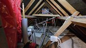
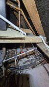
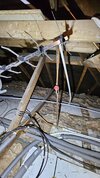
See some photos attached.

Let me know it makes sense now.
 

Attachments

  • WhatsApp Image 2024-06-09 at 10.11.12 (11).jpeg
    WhatsApp Image 2024-06-09 at 10.11.12 (11).jpeg
    278.6 KB · Views: 13
  • WhatsApp Image 2024-06-09 at 10.19.15 (7).jpeg
    WhatsApp Image 2024-06-09 at 10.19.15 (7).jpeg
    334.5 KB · Views: 11
  • WhatsApp Image 2024-06-09 at 10.19.15 (6).jpeg
    WhatsApp Image 2024-06-09 at 10.19.15 (6).jpeg
    378.2 KB · Views: 11
  • WhatsApp Image 2024-06-09 at 10.11.13 (4).jpeg
    WhatsApp Image 2024-06-09 at 10.11.13 (4).jpeg
    328.1 KB · Views: 10
  • WhatsApp Image 2024-06-09 at 10.19.15 (4).jpeg
    WhatsApp Image 2024-06-09 at 10.19.15 (4).jpeg
    314.7 KB · Views: 15
  • WhatsApp Image 2024-06-09 at 10.11.13.jpeg
    WhatsApp Image 2024-06-09 at 10.11.13.jpeg
    328.5 KB · Views: 13
  • WhatsApp Image 2024-06-09 at 10.11.12 (13).jpeg
    WhatsApp Image 2024-06-09 at 10.11.12 (13).jpeg
    346.2 KB · Views: 11
  • WhatsApp Image 2024-06-09 at 10.11.12 (12).jpeg
    WhatsApp Image 2024-06-09 at 10.11.12 (12).jpeg
    262.5 KB · Views: 14
You will have to look at it really yourself, I'm looking for something like the shetch I posted but it might be some form of combined vent and cold feed like in the attached??
 

Attachments

  • Vent & Cold Feed rev2.zip
    484.3 KB · Views: 11
Yes that is exactly what it is with your descriptions there.

It looks like a combined vent and cold feed.
 

DIYnot Local

Staff member

If you need to find a tradesperson to get your job done, please try our local search below, or if you are doing it yourself you can find suppliers local to you.

Select the supplier or trade you require, enter your location to begin your search.


Are you a trade or supplier? You can create your listing free at DIYnot Local

 
Sponsored Links
Back
Top