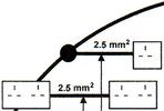
The whole idea of doing some thing so that those who follow are unlikely to make errors seems flawed. We should not assume a ring final, or radial or spur be it unfused or fused, we should test, I have seen where some one clearly jumped to the conclusion that a socket was part of a ring final when wired in 7/0.036 cable, and did it with 2.5 mm² it was a 32 amp radial, so after finding out what had happened I had to de-rate whole circuit to 20 amp. And this was on commercial premises so done by an electrician.
I liked the LAP grid sockets as a way to split the ring final to extend it, one could clip in two sockets into the double face plate, or fit a switch and 13 amp fuse plus one socket.

Main advantage is where using an existing back box, however using a twin back box allows the use of switches single sockets, but this raises the question, if in a double back box is that considered as two single sockets or a double socket?
With power on before starting if one records the loop impedance, and then once isolated and the socket is removed you test continuity to confirm a ring final, assuming no wires found loose, on replacing if you get same loop impedance readings one can be reasonably sure no wires have become detached, so no real need to remove the covers from the consumer unit to test. Theory the consumer unit should be isolated elsewhere before removing the cover, I can do this in my house, I have an isolator before the consumer unit, but in many homes, only way to obey that rule would be to draw the DNO fuse, which you should not do, as it would mean breaking the seals. OK the DNO should in theroy provide an isolator, but two wrongs don't make a right.
So better if we can do the work without opening the consumer unit, but that means you need a loop impedance meter, and most DIY people don't have one. You can get a socket tester with loop, but that is not really going to help when it passes at 1.9 Ω and the pass mark is 1.38 Ω it can show lack of earth, but they don't replace the loop impedance meter.
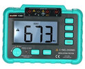
To hire around £50 as they need re-calibrating on return, to buy around £300. A multi meter to measure down to 0.001 amp AC and DC non contact is around £35, the same for a insulation tester,


but to measure low ohms using the required 200 mA, the loop impedance, or the RCD tripping times means spending out a lot more money, likely best option is to hire?
But a 13 amp fuse to BS 1362 was 2.42 Ω and the cheap (£50) plug in tester with loop, can test that, they can also test the RCD trips, although not within the 40 mS required, not even sure if the RCD test button on the plug in tester uses 30 mA?
The question is one of risk assessment, as a DIY person is doing your own electrics a risk worth taking? As already said even electricians make errors. The inspection and testing is important, I know we had three boxes of sockets, last box line and neutral swapped sides and it was missed, lucky was picked up when inspection and testing done, an easy error to make, however not testing to see if ring final or not is pretty basic. Missing a fig of 8 is still some thing not even sure needs to be tested for? The theroy is it could result load current in any part of the circuit being likely to exceed for long periods the current-carrying capacity of the cable, if the neck of the fig of 8 is near the origin, I was taught to test for fig of 8 when doing my C&G 2391, if we were to enter the readings for each socket, we may see it, but the schedule of test results does not ask for it, neither does it ask for the line - neutral loop impedance or prospective short circuit current which is required to see if volt drop is exceeded. And if not recorded then likely not tested.
The question is does any DIY'er really know how to inspect and test? When I did my course, we were all electricians, all who had been applying their trade for some time, and we had some people who failed. How can we expect the DIY'er to do effective inspection and testing if electricians after attending a 12 week night class course can fail?
Quoting the regulations is easy, interrupting them takes more skill,
BS 7671:2008 said:
433.1.5 Accessories to BS 1363 may be supplied through a ring final circuit. With or without unfused spurs, protected by a 30 A or 32 A protective device complying with BS 88-2.2. BS 88-6. BS 1361. BS 3036, BS EN 60898, BS EN 60947-2 or BS EN 61009-1 (RCBO). The circuit shall be wired with copper conductors having line and neutral conductors with a minimum cross-sectional area of 2.5 mm² except for two-core mineral insulated cables complying with BS EN 60702-1, for which the minimum cross-sectional area is 1.5 mm². Such circuits are deemed to meet the requirements of Regulation 433.1.1 if the current-carrying, capacity (Iz) of the cable is not less than 20 A and if. under the intended conditions of use, the load current in any part of the circuit is unlikely to exceed for long periods the current-carrying capacity (Iz) of the cable.
I have looked for where it says only one device allowed on an un-fused spur.
APPENDIX 15 (Informative) seems to be only place. 
Unfused spur:- An unfused spur should feed on single or one twin socket-outlet only. An unfused spur may be connected to the origin of the circuit in the distribution board
since this is "
Informative" not sure if can be regarded as a regulation?
I think this may put the pidgins where the cat is? Now I can sit back and watch the sparks fly, pun intended.


