RCD wiki + Common Misconceptions about RCDs

No, I'm familiar with those scenarios. I think I need to sleep on this one which usually works. I often wake up in the middle of the night in a moment of complete clarity. At this particular moment "wrong" has got me in a headlock :LOL:
I know the feeling.

In the meantime, may I refer you to my original post in this thread and ask if you have any comments about my wiki draft? Even though this is a 'DIY forum' I wouldn't be comfortable uploading (and wouldn't upload) anything to the wiki without getting the blessing of at least a few electricians, since I really don't think that would be appropriate.

Kind Regards, John.
 
Sponsored Links
No, I'm familiar with those scenarios. I think I need to sleep on this one which usually works. I often wake up in the middle of the night in a moment of complete clarity. At this particular moment "wrong" has got me in a headlock :LOL:
I've been thinking a little, and maybe this might help you...

I think the problem with your thought experiment may have been that it seemed to assume that N-E leakage current is a current which flows through the N side of the RCD - but it's not. It is current which is NOT flowing through the N side of the RCD (but would be in the absence of the fault/leak) because it's found an alternative path. In other words, as far as the RCD is concerned, the 'N-E leakage current' is really a 'concept', not an actual current, and that 'concept' is manifested by the current flowing through the N side of the RCD being lower than it would in the absence of the fault/leakage.

So, the appearance of an N-E fault results in the current through N side of the RCD becoming less than it was before the fault (and hence less than the L current, if L and N were equal prior to the fault). similarly, the appearance of an L-E fault results in the current through the L side of the RCD becoming more than it was before the fault (and hence more than the N current, if L and N were equal prior to the fault) - which is an imbalance in the same direction (N current less than L current) as with an N-E fault.

Hence, if N-E and L-E faults are present simultaneously, their effects are on RCD L/N imbalance are additive - since both N-E and L-E faults result in N current being lower than L current.

Kind Regards, John.
 
I can't get my head around this. If what I say is true (I'm sure I am wrong)
You are.

Look at this and tell me the RCD won't trip....

t289354.jpg


Or, if you prefer the empirical approach, take a BS 1363 plug, open it up, and connect an 11 or 12k resistor between the E&N pins, and another between E & L.

Put the top back on, plug it into an unswitched, or switched on, socket, and let us know what your RCD does.
 
Or, if you prefer the empirical approach, take a BS 1363 plug, open it up, and connect an 11 or 12k resistor between the E&N pins, and another between E & L.
Put the top back on, plug it into an unswitched, or switched on, socket, and let us know what your RCD does.
I'm not so sure about that one. The 11-12k resistor between L & E will result in an 'earth fault current' (hence RCD imbalance) of about 20mA. However, the same size resistor between N & E is obviously not going to carry anything like that amount of current, quite probably not very much current at all. Although I now accept that the two fault currents will be additive as far as RCD imbalance is concerned, I very much doubt that with your suggestion, they would add to enough to operate a 30mA RCD - I would imagine that you would need a very much lower resistance between N & E to achieve that.

Kind Regards, John.
 
Sponsored Links
Hi,

I think you'll find that a N - E fault on a circuit would affect the operation of an RCD under L - E fault conditions..........just not in the manner that you are all thinking.

Picture this, (or draw it :) ), an existing neutral/earth fault on a socket circuit.
You go to plug in your nice shiny, stainless microwave.....not noticing the frayed cable and exposed line conductor touching your hand.

Your other hand is resting on said microwave.

There's your L - E fault - but what happens to the current?

It goes via you to the microwave casing, down the CPC of the socket circuit and back down the neutral via the E - N fault.

Now there will be an imbalance, because some of the current will obviously flow to earth, but how will it affect the operation of the RCD?

Then think about the same scenario with a high resistance earth - i.e. TT.


Anyway, back on topic:

1 ........Indeed, an RCD offers NO protection to a person who comes in contact with both live and neutral conductors.

Not necessarily true - depending how well insulated your footwear is (or not), some of the current is going to flow to earth and create an imbalance.

2...An RCD will NOT trip if a two-core cable, such as that used to power many garden tools (mowers, strimmers, hedge cutters etc.) is cut.

Again, it could do, it just depends.

3...A, say, 30mA RCD does NOT limit to 30mA the current which can flow through a person in contact with live and earth. The current which flows through the person depends on circumstances, and may be much higher than 30mA. What the RCD does do is limit the duration of flow of a current of 30mA or greater can flow to a sufficient extent that serious injury/death will often (but not always) be avoided.

Obviously a 30mA RCD does not limit the current flowing from Line to Earth to 30mA........otherwise why would we bother with the 5I test?

I kind of agree with what you are saying, but I fear you may be creating your own misconception here.

Unless I've been wrong all my life, I do believe that current builds up from '0' to 'whatever', dependant on the 'Potential Difference' and the 'resistance' - In other words, we don't just instantly get 16000 Amps of fault current flowing the very millisecond that we touch 'Line' to 'Earth'............it's a build up, even if it's a very fast one.

So yes, a 30 mA RCD doesn't restrict the flow of current to 30mA - but I think it does restrict it to a degree.....and it is the disconnection time that counts.

4... Similarly, a correctly-installed RCD does NOT limit the voltage difference which can exist between the installation’s ‘earth’ system (CPCs) and true earth during fault conditions (‘touch voltage’) to 50V. Again, all it does is limit the duration of any ‘touch voltage’ greater than 50V (in practice, usually also the duration of lower voltages).

I don't really know how to argue this one except to say that there must be a reason why Zs for a 30 mA RCD has to comply with the 50V equation - otherwise, using 230V, you could have a Zs of 7666 ohms??

5... Note that, in relation to any circuits protected by single-pole RCBOs in the consumer unit, this discrimination will only exist in relation to live-earth faults, not neutral-earth ones.

I don't actually understand what you are trying to say here.
 
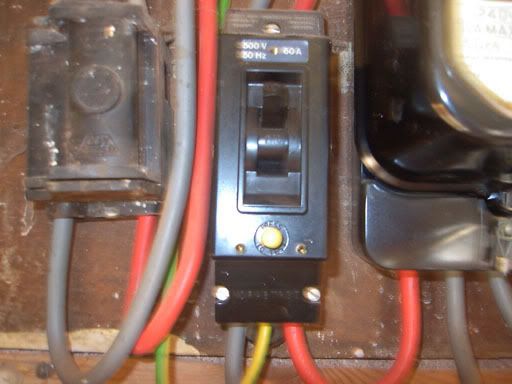
Dunno if the quality's good enough, but here's my piccy of a VO ELCB, deleted from regs in (August??) 1985:

VOELCB.jpg


Looks a bit like I took it while galloping past on a horse...
 
I think the problem with your thought experiment may have been that it seemed to assume that N-E leakage current is a current which flows through the N side of the RCD - but it's not. It is current which is NOT flowing through the N side of the RCD (but would be in the absence of the fault/leak) because it's found an alternative path. In other words, as far as the RCD is concerned, the 'N-E leakage current' is really a 'concept', not an actual current, and that 'concept' is manifested by the current flowing through the N side of the RCD being lower than it would in the absence of the fault/leakage.

Yes that is all true and that I understand, where there is a load current between L & N then say placing a resistor (to cause a 30mA current) between the output of N to E will cause N to be less than L by 30mA ------ but that is under load conditions.

My thoughts (and I am still sure I am wrong somehow)

- Take a TN-S system with say 5 volts PD between N and E.
- The origin of the 5 volts is from the supply side.
- Connect an RCD to L and N
- Measure the output of the RCD L to E= 230V - N to E = 5V
- Plug in a toaster (to a socket connected to the output of the RCD)
- At the RCD connect a 250 ohm resistance between N and E = 20mA.
- At the toaster connect a 7.6K resister between L and chassis(E) = 30mA (of course that resister could be me touching the chassis)
- The toaster is off.

Will the RCD trip?

My thoughts are that it won't trip because the current differential between L and N is only 10mA. Remove that N-E 5 volts (or remove the N-E resistor) and the RCD will trip because the current differential is now 30mA.

So I definitely understand the concept that you state John and what BAS has drawn but I am really stuck on this one. Oviously I did not need to include artifacts such as the toaster and the L-E simulated fault at the toaster but I just wanted to show that it is more than a contrived possibility/experiment. Again, I am probably wrong on this but I seem to be having a "thicker" day than usual :LOL:

This is one day where I wish I was staying in my office/workshop because I would have actually setup the experiment above but alas, I am going to look at some farm equipment that is not working!!
 
At the RCD connect a 250 ohm resistance between N and E = 20mA.
- At the toaster connect a 7.6K resister between L and chassis(E) = 30mA (of course that resister could be me touching the chassis)
- The toaster is off.
Will the RCD trip?
My thoughts are that it won't trip because the current differential between L and N is only 10mA. Remove that N-E 5 volts (or remove the N-E resistor) and the RCD will trip because the current differential is now 30mA.
Just as I said before, you again seem to be assuming that the 20mA current flowing through your N/E resistor will flow through the N side of teh RCD - but it won't. As I said, what will happen is that any pre-existing current through the N side of the RCD will be reduced by that 20mA, thereby increasing the L-N imbalance. Of course, as I said before, if there is no pre-existing load on any of the circuits connected to the RCD, there will be no N current to reduce, so your N/E resistor will have no effect - the zero current through the N side of RCD will simply remain zero when you add the N/E resistor.

...so, my suggested bottom line is that if there is some prior load on the RCD, then it will trip with your two resistors in place (since the 20mA and 30mA current will add, creating a total L/N imbalance of 50mA). If there is no prior load on the RCD, then it will still trip, because of the 30mA imbalance due to the L/E resistor, unaffected by the N/E resistor (RCD N current remains zero). If, with a pre-existing load present, you increased the L/E resistor a bit so that it was not quite enough to cause tripping on its own, then adding the N/E resistor would result in tripping, since that resistor would have the effect of reducing flow through the N side of RCD, thereby increasing the L/N imbalance to above the trip threshold.

I'm going to be out for most of today, but should be back in circulation this evening.

Kind Regards, John.
 
  • Common Misconceptions about RCDs

    1...Above all, RCDs do NOT by any means guarantee the avoidance of serious injury or death if someone comes in contact with a live conductor. Indeed, an RCD offers NO protection to a person who comes in contact with both live
  • Should be Line
    and neutral conductors. If they come in contact with a live conductor and earth (e.g. ‘earthed’ metalwork), an RCD affords some protection, but still no guarantee of immunity from serious injury or even death. Accordingly, the existence of an RCD should never be allowed to lead to complacency or relaxation of fastidious attention to safety considerations when using or working on anything electrical.

    2...An RCD will
    may rather than will
    NOT trip if a two-core cable, such as that used to power many garden tools (mowers, strimmers, hedge cutters etc.) is cut. It will, however, afford some, but not total, protection to someone who (foolishly) picks up the live end of the cable after it is cut whilst they are standing on soil or otherwise in contact with earth.

    3...A, say, 30mA RCD does NOT limit to 30mA the current which can flow through a person in contact with live and earth. The current which flows through the person depends on circumstances, and may be much higher than 30mA. What the RCD does do is limit the duration of flow of a current of 30mA or greater can flow to a sufficient extent that serious injury/death will often (but not always) be avoided.

    4... Similarly, a correctly-installed RCD does NOT limit the voltage difference which can exist between the installation’s ‘earth’ system (CPCs) and true earth during fault conditions (‘touch voltage’) to 50V. Again, all it does is limit the duration of any ‘touch voltage’ greater than 50V (in practice, usually also the duration of lower voltages).

    5...Contrary to what some people believe, a ‘TT’ electrical installations does NOT necessarily have to include a 100mA RCD close to its origin. Because of the high ‘earth fault loop impedance’ (EFLI) in TT installations, over-current protective devices such as fuses or miniature circuit breakers (MCBs) will usually not offer any protection against live-earth faults, so that such protection has to rely on RCDs. In the days when some or all of the circuits within an installation did not have their own RCD protection, the practice therefore evolved of having a 100mA RCD close to the origin of the installation. However, if (as is not uncommon these days), all final circuits in the installation have their own 30mA RCD or RCBO protection, then an additional RCD at the origin of the installation is probably not required. Without such an RCD, lack of protection only exists in relation to the tails going to the consumer unit, and the chances of a live-earth fault occurring there is extremely small provided that these tails are (as generally required by DNOs) short. If an additional RCD at the origin of an installation which contains some 30mA RCDs/RCBOs is utilised (e.g. because some of the final circuits are not RCD/RCBO-protected, or for any other reason), it should not only be a 100mA one but should also be of a ‘time-delayed’ type (‘Type S’) to ensure ‘discrimination’ between it and the 30mA RCDs/RCBOs (i.e. so it will not trip if a 30mA RCD/RCBO trips first), and must be installed in an insulated enclosure. Note that, in relation to any circuits protected by single-pole RCBOs in the consumer unit, this discrimination will only exist in relation to live-earth faults, not neutral-earth ones.
Thoughts? Any ‘misconceptions’ I have forgotten?

Kind Regards, John.
I have never worked out why we used 100 mA rather than 300 mA the latter being the required size for fire protection. But having read the post I would consider splitting into two with 4 onwards being the start of further reading.

So first let the reader get the bare bones then allow them to get more information if they want.

As to the TT problem you must first explain TT. The use of letters ELCB, RCD, RCCD, RCBO may mean something to us but to the DIY guy likely any letters will confuse him so on first use of TT (Earthing system which used an earth rod) putting short explanation in brackets from then on just use TT.

As already said picture of a ELCB-v is required I was disappointed when the yellow button was put on ELCB-c as to begin with I just asked what colour is test button.

There needs to be some explanation as to the problems with using single pole isolation afforded with some RCBO's when using a TT system or caravans and boats. I know we are allowed to use RCBO's with TT but not so sure about single pole use. See 537.2.2.1 and Table 53.2. It may comply with regulations but still not really a good idea to use single pole RCD's with a TT installation.

Maybe it needs another bit to explain isolation and that switching off a MCB or RCBO with a TT system is not isolating the supply?
 
In the circuit as drawn by Ban-All-Sheds the RCD will NOT operate but the overcurrent device should operate.

If the ground symbols refer to a ground or an earth that is connected to the supply network in some way then and only then will the RCD possibly operate and then it depends on which part of the supply network is grounded. If the supply is single phase centre tapped to earth then the RCD is un-likely to operate.

If the earth symbols refer to a CPC that is not connected to anything then the RCD will not operate.

Yes I am being very pedantic but unless one is precise and pedantic about the circuit then the effects of some faults will be predicted incorrectly and then the safety procedures for protection for when that fault occurs will therefore also be incorrect
 
It's a regular single-phase TN or TT supply, and the symbols refer to actual terra firma.

Sorry - should have made that clear - it was late.

The point I was trying to make was that the faults in no way cancel each other out.
 
1 ........Indeed, an RCD offers NO protection to a person who comes in contact with both live and neutral conductors.
Not necessarily true - depending how well insulated your footwear is (or not), some of the current is going to flow to earth and create an imbalance.
Agreed. Lots of possible ways to deal with that. Maybe "...an RCD usually offers NO protection...", or maybe "...in contact with only live and neutral conductors...", or perhaps "...in contact with both live and neutral conductors, but not with any path to earth", or ..... What do you think.

2...An RCD will NOT trip if a two-core cable, such as that used to power many garden tools (mowers, strimmers, hedge cutters etc.) is cut.
Again, it could do, it just depends.
That one has already been raised (by westie). Probably the best solution is "...will not necessarily trip....".

3...A, say, 30mA RCD does NOT limit to 30mA the current which can flow through a person in contact with live and earth. The current which flows through the person depends on circumstances, and may be much higher than 30mA. What the RCD does do is limit the duration of flow of a current of 30mA or greater can flow to a sufficient extent that serious injury/death will often (but not always) be avoided.
Obviously a 30mA RCD does not limit the current flowing from Line to Earth to 30mA........otherwise why would we bother with the 5I test?
You may well think it is obvious, as do I - but this is one that I have heard a good few times from the lips/pens of electricians.

I kind of agree with what you are saying, but I fear you may be creating your own misconception here.
Unless I've been wrong all my life, I do believe that current builds up from '0' to 'whatever', dependant on the 'Potential Difference' and the 'resistance' - In other words, we don't just instantly get 16000 Amps of fault current flowing the very millisecond that we touch 'Line' to 'Earth'............it's a build up, even if it's a very fast one. So yes, a 30 mA RCD doesn't restrict the flow of current to 30mA - but I think it does restrict it to a degree.....and it is the disconnection time that counts.
I fear that you have probably been essentially wrong all your life :) As far as I aw aware, there is nothing in the circuits we are talking about which has the ability to slow down the 'build-up' of AC current in the way you suggest. If you were right, then Ohm's Law would be violated (for a given 'resistance' and 'pd') until the 'build up process' had been completed. Some may nitpick and talk about the instantaneous current - depending upon the exact timing of the appearance of the fault, it could obvioulsy take anything up to quarter of a cycle (5ms at 50Hz) for the instantaneous current to reach its peak.

4... Similarly, a correctly-installed RCD does NOT limit the voltage difference which can exist between the installation’s ‘earth’ system (CPCs) and true earth during fault conditions (‘touch voltage’) to 50V. Again, all it does is limit the duration of any ‘touch voltage’ greater than 50V (in practice, usually also the duration of lower voltages).
I don't really know how to argue this one except to say that there must be a reason why Zs for a 30 mA RCD has to comply with the 50V equation - otherwise, using 230V, you could have a Zs of 7666 ohms??
It's really the same situation as with current (above). Zs for a 30mA RCD has to 'comply with the 50V equation' in order to guarantee that disconnection will occur (within an acceptable time limit) if there is a 'touch voltage' of 50V or more. However,as with current, the full touch voltage (as determined by Ohm's and/or Kirchoff's Laws) will appear 'immediately' the fault appears, and will remain at that level (which could be considerably more than 50V, particularly with TT) during the brief period before disconnection occurs.

5... Note that, in relation to any circuits protected by single-pole RCBOs in the consumer unit, this discrimination will only exist in relation to live-earth faults, not neutral-earth ones.
I don't actually understand what you are trying to say here.
Simple. Given a 30 mA SP RCBO protecting a final circuit and a preceding ('upstream') 100 mA Type S RCD, if a L-E fault occurs on the final circuit, the RCBO will operate and disconnect the L (thus eliminating the fault) and therefore the delayed RCD will not operate - i.e. discrimination. However, if there is a N-E fault on the circuit, the SP RCBO will operate, but since it does not disconnect neutral, the fault will persist, and the RCD will (provided that there is some load on the installation) operate after its brief time delay - i.e.no discrimination.

Kind Regards, John.
 
....Indeed, an RCD offers NO protection to a person who comes in contact with both live ....
Should be Line
I thought long and hard about this one, since I knew someone would raise it. I personally think that most members of the public, including many/most electrical DIYers, will talk about and understand 'live', but not necessarily 'line'. What do others think?

2...An RCD will
may rather than will
NOT trip if a two-core cable...
This has been agreed - "...may NOT trip..." or "will NOT necessarily..."

I have never worked out why we used 100 mA rather than 300 mA the latter being the required size for fire protection.
We've discussed that before, and I suspect the answer is historical, since I think 100mA corresponds roughly to the trip point of the VOELCBs which preceded RCDs - but I may be wrong. Turning the argument the other way around, when we got to the stage that some (but not all) final circuits were RCD protected, why not an upstream 30mA Type S RCD in TT systems?

But having read the post I would consider splitting into two with 4 onwards being the start of further reading. .... So first let the reader get the bare bones then allow them to get more information if they want.
Yes, it may benefit from being split into sections.

As to the TT problem you must first explain TT. The use of letters ELCB, RCD, RCCD, RCBO may mean something to us but to the DIY guy likely any letters will confuse him so on first use of TT (Earthing system which used an earth rod) putting short explanation in brackets from then on just use TT.
Indeed, I'll go through and make it DIYer-friendly; I was trying (as with 'live', rather than 'line') but missed a few things that needed explaining.

There needs to be some explanation as to the problems with using single pole isolation afforded with some RCBO's when using a TT system or caravans and boats. I know we are allowed to use RCBO's with TT but not so sure about single pole use. See 537.2.2.1 and Table 53.2. It may comply with regulations but still not really a good idea to use single pole RCD's with a TT installation.
Maybe it needs another bit to explain isolation and that switching off a MCB or RCBO with a TT system is not isolating the supply?
I have touched on the TT/SP RCBO issue, but it could be expanded. However, I think all this may be yet another article, since it hardly counts as 'misconceptions about RCDs' :)

Kind Regards, John
 
I fear that you have probably been essentially wrong all your life :) As far as I aw aware, there is nothing in the circuits we are talking about which has the ability to slow down the 'build-up' of AC current in the way you suggest.

Correct, we are not talking highly inductive circuits here, the current will rise as fast as the resistance drops. If a human body completes a circuit between L and E then the maximum current will flow almost instantaneously. As you say in these circumstances no later then quarter of a cycle.
 

DIYnot Local

Staff member

If you need to find a tradesperson to get your job done, please try our local search below, or if you are doing it yourself you can find suppliers local to you.

Select the supplier or trade you require, enter your location to begin your search.


Are you a trade or supplier? You can create your listing free at DIYnot Local

 
Sponsored Links
Back
Top