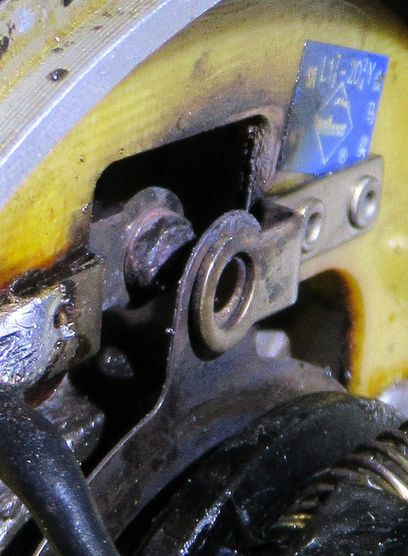
That seems rather a small capacitor to be in the order of 190uF Could you please show a photograph of the information that's printed on it.
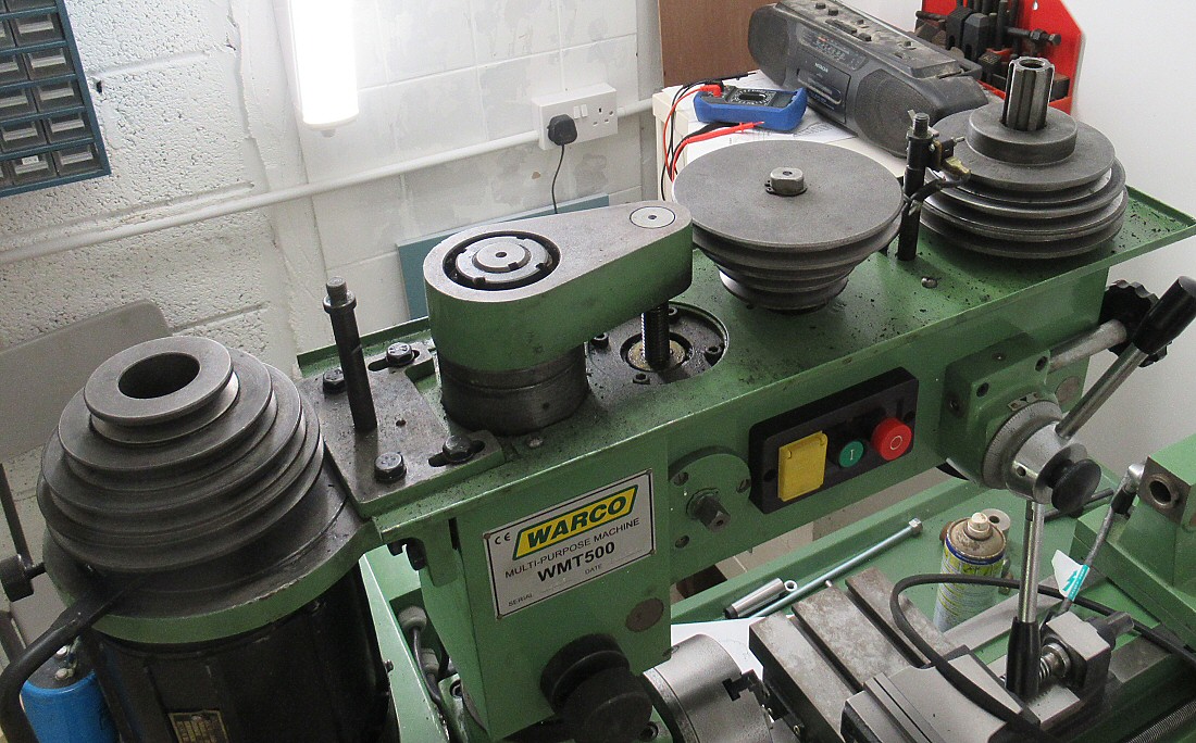
It could be that the belts running in one direction tend to slacken away from the drive pulley and decrease the wrap so increasing the belt slip and allowing the motor to get up to speed. In the opposite direction the belts could 'wind up' increasing the wrap on the drive pulley, dereasing belt slip, and hence increasing the start load and preventing the motor getting up to speed.
It could be that the belts running in one direction tend to slacken away from the drive pulley and decrease the wrap so increasing the belt slip and allowing the motor to get up to speed. In the opposite direction the belts could 'wind up' increasing the wrap on the drive pulley, dereasing belt slip, and hence increasing the start load and preventing the motor getting up to speed.