Samsung ue65nu8000T not powering up

Joined
30 Mar 2015
Messages
4,129
Reaction score
64
Country
United Kingdom
Can I get some advice with this please.

I get no sign of life when I switch this TV on. I’ve tried holding down the power button in various fashions but that hasn’t booted it up. The fuse on the plug and socket are fine.

I’ve opened it up and have this:
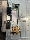
IMG_4578.jpeg

I’ve put my two pole tester on the fuse next to the power inlet and a bunch of other fuses/capacitors on this board and all have continuity.
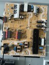
IMG_4582.jpeg

Except, this green “thingy”, to the right of the fuse. When I put the probes on each leg, there is no continuity. Should there be?

I then switched in the TV and used my contactless tester (I appreciate it’s not a great tester) but this shows power on the power supply board and the main board too.

I then disconnected this cable going between the two boards and powered up again
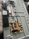
IMG_4581.jpeg

I read that this may bring the backlight to life. Not for me :(.

Have I got a dodgy power supply board or is this way too inconclusive? I would welcome your suggestions on how to resolve this.

Thanks in advance.
 
Sponsored Links
Except, this green “thingy”, to the right of the fuse. When I put the probes on each leg, there is no continuity. Should there be?
The green 'thingy' appears to be an NTC (Negative Temperature coefficient) thermistor - a device that decreases its resistance with increasing temperature.
There may not be 'continuity' across the NTC, but there should be a measurable resistance - maybe around 10KOhms at room temperature?
Can you check resistance with your tester?
 
...and just looking closer, the power PCB was manufactured in 2018.
Samsung offered a free 5 year extended warranty (with registration), on some TVs.
How old is the TV, did you register an extended warranty?
 
Unfortunately, not covered by warranty. I did call Samsung. Good shout!

I have a 2 pole tester and a megger MFT. Would either of those help @RandomGrinch?

I’ve seen that a new power supply board is around £40 and they seem straight forward to replace. Will await some more advice before I take that punt.

Thanks for your help.
 
Sponsored Links
I have a 2 pole tester and a megger MFT. Would either of those help
What makes/models?
Although the question then becomes, if you do find a dodgy component, do you have the soldering tools to swap it out?
At least it may prove that the board has failed.
I’ve seen that a new power supply board is around £40 and they seem straight forward to replace. Will await some more advice before I take that punt.
It may be worth a gamble, you could probably put it back on eBay if you didn't get anywhere?
 
If I was you, I'd buy a new TV.

Wrangling around power supplies is dangerous especially if you don't really know what you're doing.
 
Last edited:
What makes/models?
Fluke T130 for 2 pole tester and megger MFT 1711 for the MFT.
At least it may prove that the board has failed.
That’s what I was thinking. It would be good to validate that the board is faulty. I can then swap the board out.

It may be worth a gamble, you could probably put it back on eBay if you didn't get anywhere?
Happy to get the board if there is a realistic prospect of this being at fault based on the info I have shared. Appreciate it’s not guaranteed but didn’t know whether my information is just way too inconclusive to make that leap.

Thanks again.
 
Is the power switch just that or is it a joystick one that controls other features Have you tried NEW batteries in your remote not some you had in a drawer and have you tried powering up at the power switch with the batteries removed
 
UPDATE: I replaced the power supply board and bingo! TV works.

The issue was apparent when I saw the back of the Power Supply Board.
IMG_4611.jpeg

That burn mark is actually visible in my earlier image too. Here it is:

IMG_4582.jpeg

Now, any ideas on what this component is and what may have caused the fault?

Thanks for your help with this.
 
Brilliant, well done! :)
Thanks for letting us know.

That burn mark is actually visible in my earlier image too. Here it is:
The irony is, I had noticed that patch on the PCB - although it is right by the 'Hot' symbol, so it didn't sink in.
The problem is, 'Hot' in this case means the "Low voltage" side of the board compared to the 'Cold', "Extra low voltage" side! :LOL:

Now, any ideas on what this component is and what may have caused the fault?
A better photo may help identify it, but I doubt we'll get anywhere - there may well also be damaged to the PCB traces.
 
Last edited:
Here's the reverse of an undamaged PCB...
1727871588419.jpeg

My interpretation is purely guesswork, I haven't found a schematic and I am definitely no expert, so I may be completely wrong!

From the mains input, and ignoring the fuse, NTC and a couple of inductors, the mains feeds into a bridge rectifier.
Before it reaches the rectifier, there are a couple of components bridging L and N...

PCB2.png


I'm not sure which, but these may be a resistance voltage divider, or a two diode rectifier.
The trace then reaches the scorched area...

PCB1.png


these turn out to be a couple of passive components. From the scorch marks, I was expecting a transistor, but it appears they are a couple of voltage dropping resistors.
The trace then leads to a couple more passives and an IC (maybe for its power supply)...

PCB3.png


All I can do is speculate...

The main failure mode for chip resistors is to fail open, due to exceeding their wattage rating, or more rarely, exceeding their voltage rating.
That may suggest that a short, or problem with the IC (or some component further along the circuit), caused excess current to be drawn through the resistors.
Alternatively, a power surge through the mains, could have exceeded the resistors voltage rating.

Where this trace begins, is the very first branch off of the mains supply, before primary rectification and smoothing.
This suggests that the IC is one of the very first components in the logic chain that enables the supply. I.e. it could be a chip that would enable the power supply to wake from standby, when other ICs aren't receiving power, or it could be monitoring the incoming supply.
Also, as it is (almost) directly connected to the mains, rather than being behind the primary rectification and smoothing, the IC supply is at a higher risk of damage, than other parts of the circuit.would be.

But again, I could be completely wrong! :)

...I wonder if you can see any markings on the IC?
 
Last edited:

DIYnot Local

Staff member

If you need to find a tradesperson to get your job done, please try our local search below, or if you are doing it yourself you can find suppliers local to you.

Select the supplier or trade you require, enter your location to begin your search.


Are you a trade or supplier? You can create your listing free at DIYnot Local

 
Sponsored Links
Back
Top