Smart thermostats receive no power after switching from battery-operated thermostats

Joined
29 Oct 2023
Messages
7
Reaction score
3
Country
United Kingdom
Good morning,

I'll preface this by saying the majority of my knowledge on this topic is just what I have read around the internet. I'm not an electrician, the most I've done (aside from failing to change my thermostats) is change a socket. But I've tried to find as much information as possible to provide here.

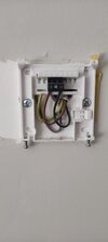
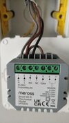
I recently won the Amazon warehouse lottery and got my hands on 2 Meross smart thermostats for half price and was hoping to get them wired up. I currently have dual-zone heating in my new build using the thermostats provided by the developer. A Salus RT510 downstairs and RT520 upstairs (I have no idea why they used different models, new build developers and logic are not often found together). I turned the power to the central heating off and removed the 510 (I've attached a photo of the 510 wiring, the exposed copper on the brown wire was how it was fitted and has since been fixed). After installing a backbox, I wired up the Meross stat following a combination of advice from my brother-in-law (who is a sparky) and google (again, I've provided an image to show what I did). I only wanted to test the downstairs thermostat before working upstairs and I am glad I did because when I turned the power back on, no power went to the new thermostat. Wiring the old thermostat back up again worked fine. It's worth noting that the Salus RT520 upstairs has a similar wiring setup, 3 core and earth cable but only brown and black wired up to COM and NO respectively.

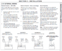
So this is where I started reading around. To start, my brother-in-law is currently away, so if push comes to shove, I can wait a week to get him to help if this is something I can't do. My current thermostats are battery powered, so they (from my understanding) do not need to be powered via the boiler (volt-free I think it's called?). However, I can change the wiring on my boiler to provide mains power to my thermostats (I've attached what I believe to be the relevant section of the boilers documentation).

So my questions are:
1) Are my assumptions here correct? All I need to do is change my boilers wiring setup to be live?
2) Provided my assumptions are correct, is this something I could do myself? Or am I best waiting until my BiL returns from holiday?
3) I dont plan on living in this house forever, I'll eventually move and will likely take the smart stats with me. Will I need to change the wiring back to volt free for the old stats or can the battery operated stats operate fine with the live wire being actually live?

Thank you for any help and apologies if I've made any mistakes or incorrect assumptions.
 

Attachments

  • salus 510 wiring.jpg
    salus 510 wiring.jpg
    69.7 KB · Views: 150
  • new meross wiring.jpg
    new meross wiring.jpg
    183.8 KB · Views: 358
  • Logic Wiring.png
    Logic Wiring.png
    112.1 KB · Views: 133
Sponsored Links
I would suspect that the grey core is not connected as a neutral, luckily you have it there at all, especially with housing estate developers involved!. If you have a multimeter?, you would be able to prove this.

If the black is a switched live, it should be sleeved brown, and if you are now making the grey a neutral, you will need to sleeve it blue (both ends0

You need to find out where the 3+E cables from the stats go, I should imagine there will be a wiring centre somewhere, as the stats will be controlling motorised valves, which then in turn bring the boiler on. You need to find this (photos please). In the airing cupboard, or under the boiler are good places to look.
 
2.19.3could be the section you require but personally I'd say wait as there is likely to be more wiring than the basic hinted at in the manual.
 
I would suspect that the grey core is not connected as a neutral, luckily you have it there at all, especially with housing estate developers involved!. If you have a multimeter?, you would be able to prove this.

If the black is a switched live, it should be sleeved brown, and if you are now making the grey a neutral, you will need to sleeve it blue (both ends0

You need to find out where the 3+E cables from the stats go, I should imagine there will be a wiring centre somewhere, as the stats will be controlling motorised valves, which then in turn bring the boiler on. You need to find this (photos please). In the airing cupboard, or under the boiler are good places to look.

Oh so they'll be going to the valves themselves! I actually know where they are because one broke and was stuck permanently on a few Christmases ago. They are believe it or not, under the bath! I'm guessing the wiring centre will be what I think is a cracked 2 gang backbox in there? I'm out at the moment but I'll try and get under there when I get home.

As for the multimeter question, I do have one I picked up to make sure I wasn't gonna blow myself up before changing a socket. I'm guessing you'd want me to turn the power off, remove the stat, power back on and then red probe the grey cable?
 
Sponsored Links
You want to see if you have 240v between brown and grey (also check between brown and earth)
May as well test black to grey and black to earth as well

Be careful that your multimeter has got the probes in the voltage socket and is set to an AC voltage high enough. Also watch out for the probes, a lot of cheap ones have a lot of exposed metal on the tips.

The wiring centre could be in a cracked backbox under the bath, I'd consider that very poor on a new build property though!
 
Bear in mind that your stat wiring will not get any volts until the heating programmer has reached the on period!
When (if) you get the Meross ones working you'll set the times on the Meross app.
Your existing heating time clock will need to be set to ALWAYS ON>?
 
I would have expected 7 wires to the thermostat with a home using zone valves and a opentherm enabled boiler, likely a 5 core and 2 core the 5 core to motorised valves and two core to boiler. This
1699257670525.png
is wiring to motorised valves, and this
1699257785139.png
is the wiring to the boiler. With a combi boiler the HW is not used, but you still need the three channel to get the two motorised valves, shown is wiser by Drayton, which allows use of programmable TRV heads, EPL do a version with master/slave thermostats again wired to both motorised valves and boiler, there may be other makes, but I am unaware of them.

One can lash together other thermostats which will work, but not economically, main point is central heating needs to have analogue control, TRV's slowly open and close allowing the boiler to modulate to match the output required, and gain the latent heat, on/off controls stop the boiler gaining the latent heat, they are required to turn off boiler when temperature requirements have changed or the weather warms up, to stop boiler cycling.

It can be done on the cheap with on/off thermostats, but it takes a lot of setting up, to ensure the thermostat and TRV work in harmony and don't fight each other.

There are good reasons for using motorised valves, I have one that controls the flat and one controls main house, but within the main house, we use bedrooms as craft room and office, and dining room as bedroom, and to split upper and lower floor into two zones is unworkable. I want each room as its own zone, so have 9 programmable TRV heads, at moment two wall thermostats, one in flat and one in main house, but really need a third as my TRV heads don't link to the wall thermostat.

So you have to it seems alter the wiring, so step one is decide on your final goal so you only do it once. Personally I would simply use a battery powered thermostat. But there are methods which can use two wires for multi controls, I use Nest Gen 3 because I only have two wires between boiler and main house, It is a three core cable, but one core open circuit, so the Nest uses two 12 volt wires which keep the battery in the thermostat charged, and also send data to the main controller to tell it what to do, however I am not a lover of Nest it will not connect to TRV heads.

You want everything to do with central heating to be either battery or from one circuit, one for safety so turn off one FCU or unplug one plug turns all off, and second so if you ever fit solar panels with a battery the central heating can be battery backed, having a thermostat powered with a USB power supply and the USB coming from a wallmart plugged into normal socket would mean with power cut central heating still fails.

Likely you can find the grey wire and connect it to neutral, which is a good temporary fix, but you need to be moving from digital to analogue with a modulating gas boiler, I don't have that option I am using oil.
 
Interesting! plug featured in the meross web home page banner.i have circled it in red.
bce24aa916a4f6f2ee14fee76f4e8951.w1920.h384._CR0,0,1920,384_SX1920_.jpg
 
Hello I'll try to get through some of these now.
You want to see if you have 240v between brown and grey (also check between brown and earth)
May as well test black to grey and black to earth as well

Be careful that your multimeter has got the probes in the voltage socket and is set to an AC voltage high enough. Also watch out for the probes, a lot of cheap ones have a lot of exposed metal on the tips.

The wiring centre could be in a cracked backbox under the bath, I'd consider that very poor on a new build property though!
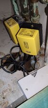
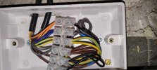
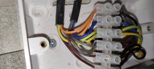
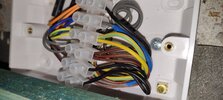
My new build is a mess to be honest. I don't know if I'd ever go for one of these again. I haven't had time to get the multimeter on the wiring centre but I did get a photo under the bath. I didn't remember the crack being so bad on the blank faceplate. I'll go to screwfix after work and get a replacement. Then I'll try and get you photos and a reading. In the meantime, I've attached what I saw.

Bear in mind that your stat wiring will not get any volts until the heating programmer has reached the on period!
When (if) you get the Meross ones working you'll set the times on the Meross app.
Your existing heating time clock will need to be set to ALWAYS ON>?
I am not aware of any time clock. As far as I know, I have the living room controller which switches on all downstairs and the main bedroom controller which switches on all upstairs.

I would have expected 7 wires to the thermostat with a home using zone valves ana a opentherm enabled boiler, likely a 5 core and 2 core the 5 core to motorised valves and two core to boiler. ThisView attachment 319914is wiring to motorised valves, and this View attachment 319915is the wiring to the boiler. With a combi boiler the HW is not used, but you still need the three channel to get the two motorised valves, shown is wiser by Drayton, which allows use of programmable TRV heads, EPL do a version with master/slave thermostats again wired to both motorised valves and boiler, there may be other makes, but I am unaware of them.

One can lash together other thermostats which will work, but not economically, main point is central heating needs to have analogue control, TRV's slowly open and close allowing the boiler to modulate to match the output required, and gain the latent heat, on/off controls stop the boiler gaining the latent heat, they are required to turn off boiler when temperature requirements have changed or the weather warms up, to stop boiler cycling.

It can be done on the cheap with on/off thermostats, but it takes a lot of setting up, to ensure the thermostat and TRV work in harmony and don't fight each other.

There are good reasons for using motorised valves, I have one that controls the flat and one controls main house, but within the main house, we use bedrooms as craft room and office, and dining room as bedroom, and to split upper and lower floor into two zones is unworkable. I want each room as its own zone, so have 9 programmable TRV heads, at moment two wall thermostats, one in flat and one in main house, but really need a third as my TRV heads don't link to the wall thermostat.

So you have to it seems alter the wiring, so step one is decide on your final goal so you only do it once. Personally I would simply use a battery powered thermostat. But there are methods which can use two wires for multi controls, I use Nest Gen 3 because I only have two wires between boiler and main house, It is a three core cable, but one core open circuit, so the Nest uses two 12 volt wires which keep the battery in the thermostat charged, and also send data to the main controller to tell it what to do, however I am not a lover of Nest it will not connect to TRV heads.

You want everything to do with central heating to be either battery or from one circuit, one for safety so turn off one FCU or unplug one plug turns all off, and second so if you ever fit solar panels with a battery the central heating can be battery backed, having a thermostat powered with a USB power supply and the USB coming from a wallmart plugged into normal socket would mean with power cut central heating still fails.

Likely you can find the grey wire and connect it to neutral, which is a good temporary fix, but you need to be moving from digital to analogue with a modulating gas boiler, I don't have that option I am using oil.
Right, that sounds very complicated. Almost to the point that having a thermostat that I can control and monitor via my phone and alexa isn't really worth the hassle. I only went with these because I have their smart TRVs all over the house.

Interesting! plug featured in the meross web home page banner.i have circled it in red.View attachment 319939
Meross do a number of smart devices. I'm sorry I don't understand what I'm looking at here.
 

Attachments

  • IMG_20231106_115055.jpg
    IMG_20231106_115055.jpg
    220.2 KB · Views: 86
Data sheet for valve here it has a fixed colour code
1699275480801.png
this makes it easier working out what does what in the wiring centre (Back box and blanking plate) the Orange and Grey go to boiler and the brown comes from the thermostat the motorised valve acts as a relay as well as a valve.

I can see @Sureitsoff? point they show a 13 amp socket upside down, there is nothing to say you should not do this, but it means cable entry is on the top, and many plugs will not have the required IP rating if used upside down.

I have watched the Meross video and I am impressed, seems you have made a good choice, but I look at the wiring diagram
1699276384729.png
and note the sensor, normally only used with under floor heating, so stop floor getting too hot, but it shows it in use with the gas boiler version, I at first thought all you lacked was the neutral, but I don't see the sensor connected?

Personally I would get rid of the zones and connect the two valves together, but that is some thing for the future, first lets get it working.

So connect a meter to L and N and see if 230 volt, if no meter a table light will do. Wire it into L and N and see if it lights. but reading the installation manual it does seem the sensor needs to be connected.
 
and note the sensor, normally only used with under floor heating, so stop floor getting too hot, but it shows it in use with the gas boiler version, I at first thought all you lacked was the neutral, but I don't see the sensor connected?
I dont think that it is trying to show a floor sensor.

A sensor is optional, remember that it could be a remote room AIR sensor. The Meross will have the option (as most do) of being able to select tempewrature as room air, or sensor or both.
 
I dont think that it is trying to show a floor sensor.

A sensor is optional, remember that it could be a remote room AIR sensor. The Meross will have the option (as most do) of being able to select tempewrature as room air, or sensor or both.

So this is correct. The sensor is optional and not required as the thermostat itself can do an air temp reading. The sensor is incase you'd rather it read something else, which I don't think I need.

OK so I've got a photo of the wiring under the bath. This is where you want me to test with the multimeter?

Edit: added some more angles because the box is partially obscured by a batten so it's not exactly easy to photograph.
 

Attachments

  • IMG_20231106_173243.jpg
    IMG_20231106_173243.jpg
    188.3 KB · Views: 56
  • IMG_20231106_174657.jpg
    IMG_20231106_174657.jpg
    156.3 KB · Views: 50
  • IMG_20231106_174635.jpg
    IMG_20231106_174635.jpg
    197.8 KB · Views: 54

DIYnot Local

Staff member

If you need to find a tradesperson to get your job done, please try our local search below, or if you are doing it yourself you can find suppliers local to you.

Select the supplier or trade you require, enter your location to begin your search.


Are you a trade or supplier? You can create your listing free at DIYnot Local

 
Sponsored Links
Back
Top