Switch and flood light issue
- Thread starter Hyperway
- Start date
Sponsored Links
It is a pair of pulse operated switches, one pulse to turn a switch on , then a second pulse will switch it off
Switching relay AC 253...207V 10A - Pulse switch RDS U1
Switching relay AC 253...207V 10A - Pulse switch RDS U1
Oh dear.
I'll get me coat.
I'll get me coat.
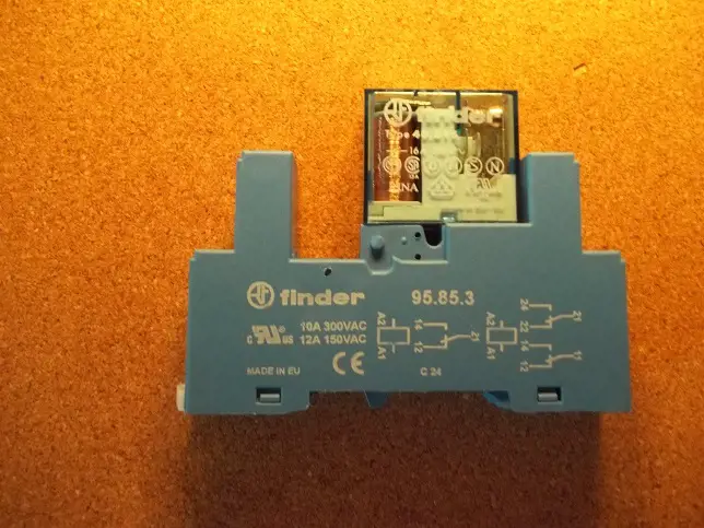
My drawing was for the relay I suggested.Thanks for diagram, so A1 live A2 neutral… is B1 not used? Are you able to draw on this photo easy for me to understand? Thank you
This would be better:
To prevent an active (or faulty) pir to hold the relay on when override switch is released.[/S]
EDIT: Written before i saw last few posts.
I suggest go back to Screwfix relay (contactor), Bernards enclosure and circuit in posts #20, #22 & #25.
Last edited:
Sponsored Links
When you switch the override off, Sometimes you may find all the lights stay on if one of the PIR's is triggered. It's not a fault, just a quirk of the way it's wired.Just to say I purchased the screwfix option suggested by Sunray, wired as EFLImpudence diagram. Happy to confirm working exactly as described. Thank you all that contributed to the thread, really appreciate the support.
Last edited:
How so ? That implies that with the relay on, a supply from one of the PIRs can hold it on - but the switch is in the supply to the relay coil so with the switch off, there's no route for that circuit.When you switch the override off, Sometimes you may find all the lights stay on if one of the PIR's is triggered. It's not a fault, just a quirk of the way it's wired.
There is when the relay is energised.How so ? That implies that with the relay on, a supply from one of the PIRs can hold it on - but the switch is in the supply to the relay coil so with the switch off, there's no route for that circuit.
Are we talking about the same setup ?There is when the relay is energised.
Open the switch, there is then no connection to A1, therefore no current through the coil, relay opens - regardless fo state of the PIRs.I suggest go back to Screwfix relay (contactor), Bernards enclosure and circuit in posts #20, #22 & #25.
View attachment 264097
This is what has been installed

Override operated (red contact positions) provides 3 current paths in orange

Then PIR 1 triggers (Pink) providing potential additional current pathes in purple

Then override switch off leaves the 3 purple paths

Override operated (red contact positions) provides 3 current paths in orange
Then PIR 1 triggers (Pink) providing potential additional current pathes in purple
Then override switch off leaves the 3 purple paths
Last edited:
So, no we're not talking about the same setup then. I'd have done it as you drew it.This is what has been installedAre we talking about the same setup ?
Just to say I purchased the screwfix option suggested by Sunray, wired as EFLImpudence diagram.
Happy to confirm working exactly as described. Thank you all that contributed to the thread, really appreciate the support.
I'd have preferred that but I don't know how the existing is cabled and wired, it may not be easy.So, no we're not talking about the same setup then. I'd have done it as you drew it.
DIYnot Local
Staff member
If you need to find a tradesperson to get your job done, please try our local search below, or if you are doing it yourself you can find suppliers local to you.
Select the supplier or trade you require, enter your location to begin your search.
Please select a service and enter a location to continue...
Are you a trade or supplier? You can create your listing free at DIYnot Local
Sponsored Links


