DC Current shunts

Joined
11 Jun 2005
Messages
186
Reaction score
17
Location
Lancashire
Country
United Kingdom
Hi,

I know it's not a question about 'utility power' but thought I'd post anyway...

I am having trouble with a DC current shunt connected on an auxiliary battery on my vehicle.

At night when there is no current draw and I calibrate the shunt by zeroing the meter and then putting a 150amp load on and calibrating it all is fine.

BUT come the morning the meter is showing a current of 0.4amps flowing into the battery. There is a quiescent current of something like 0.01amps from electronics etc flowing all the time, but why the difference; could it be down to temperature as the shunt is located on top of the battery in the engine compartment so is subject to temperature changes.

If so, any simple ideas to negate it?

Thanks,

Ian
 
Sponsored Links
I am having trouble with a DC current shunt connected on an auxiliary battery on my vehicle.
At night when there is no current draw and I calibrate the shunt by zeroing the meter and then putting a 150amp load on and calibrating it all is fine.
BUT come the morning the meter is showing a current of 0.4amps flowing into the battery. There is a quiescent current of something like 0.01amps from electronics etc flowing all the time, but why the difference; could it be down to temperature as the shunt is located on top of the battery in the engine compartment so is subject to temperature changes.
Assuming that I understand correctly (do I take it that this shunt is in series with the auxillary battery, for metering purposes?) ... do I take it that there are diodes involved in the set-up? If not, there would almost always be current flowing between primary and auxillary batteries (one way or the other), and that current would vary all the time (depending on relative voltages of the two batteries, which can vary for umpteen reasons).

Temperature changes will certainly alter the resistance of the shunt, but they can't make substantial currents appear from nowhere. Temperature changes can also alter the voltages of one or both batteries, which would alter any current flowing between them.

Kind Regards, John
 
The shunt is in series with the -ve connection to the battery.

I should have said that when the engine is not running this auxiliary battery is isolated from the main battery so there shouldn't be any current flowing between the batteries.

To be honest I'm not too bothered about an inaccuracy at idle of such small magnitude, the only problem is it gives a false reading of battery capacity as the meter measures the remaining battery capacity as a product of the current flows in and out. It would be good if I could remove any small readings such as this but the meter won't allow it.

Are you saying that the temperature change probably wouldn't cause this?
 
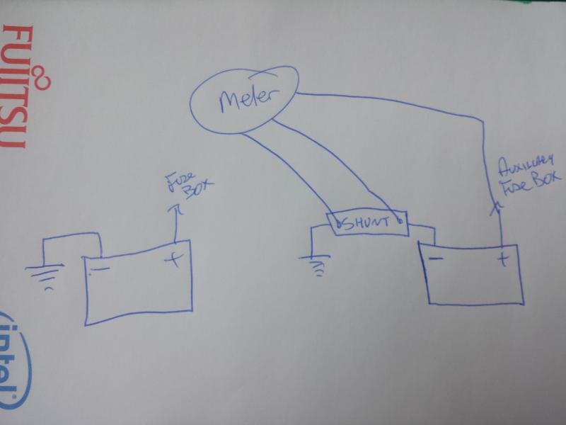
Can you supply a circuit of how your shunt, the arduino and the normal vehicle battery systems are connected. Your question is an interesting one but without a circuit answers are pure speculation.
 
Sponsored Links
I should have said that when the engine is not running this auxiliary battery is isolated from the main battery so there shouldn't be any current flowing between the batteries.
Fair enough, but if current is flowing through the shunt, it must be going somewhere - so, if the auxillary battery is not connected to the other battery when the engine is off, what is it connected to?
Are you saying that the temperature change probably wouldn't cause this?
Temperature changes could result in small changes in the resistance of the shunt, hence small changes in the voltage measured across it (which I presume is what you're doing) - but, as I said, it obviously cannot make current appear from nowhere.

We'd really need a lot more detail about your set-up before we could give more useful suggestions.

Kind Regards, John
 
Sure, apologies for the very rough sketch but you should get the idea!
Thanks - but my question remains - what is connected to that battery (when engine off) via the 'auxillary fuse box'?

We would really need details of the 'meter' and what goes on inside it. If it is really true that there is no significant current flow, it might well just be that (given it measures up to at least 150A), the 0.4A measurement you're seeing is simply a small variation in what the meter displays for 'zero current', due to slight instability of the meter circuit's zero setting.

Kind Regards,
 
Thanks, overnight actually powered up is just a clock, everything else is isolated.

The meter can measure up to 500A so I agree it is likely to not be particularly accurate at readings around zero. It would just be nice to be able to zero it.
 
If the current is not zero and you zero it at meter this could cause the problem. I would measure with independent meter and set your meter at the actual amps drawn.

I have in the past been caught out where current it drawn from an item I have never thought of.
 
Thanks, overnight actually powered up is just a clock, everything else is isolated.
OK, so the true current is essentially zero.
The meter can measure up to 500A so I agree it is likely to not be particularly accurate at readings around zero. It would just be nice to be able to zero it.
If the meter can measure to 500A and its circuitry is such that the zero can vary, then a drift of 0.4A in the zero reading (0.08% of FSD) is far from unexpected, and could easily be due to temperature changes or other things. However, it's rather odd, since such circuitry really shouldn't be such that the 'zero reading' could be anything but zero. Is it a commercial 'meter' or something that you have constructed? Can you (or do you have to) 'set' the zero reading?

Kind Regards, John
 
As said that error is very small and probably not worth bothering about.

I think the error is probably due to thermo-couple effects between the metal of the shunt and the metal of the leads from shunt to meter producing a few milli-volts of voltage to the meter even though the voltage across the shunt is zero.

If accuracy at low current is essential then the meter will need a means to compensate for these thermo-couple errors.
 
Can you tell us more about this current-measuring shunt? i.e. URL, name, or photo?
 

DIYnot Local

Staff member

If you need to find a tradesperson to get your job done, please try our local search below, or if you are doing it yourself you can find suppliers local to you.

Select the supplier or trade you require, enter your location to begin your search.


Are you a trade or supplier? You can create your listing free at DIYnot Local

 
Sponsored Links
Back
Top