
You are using an out of date browser. It may not display this or other websites correctly.
You should upgrade or use an alternative browser.
You should upgrade or use an alternative browser.
Grant oil boiler hunting
- Thread starter George J
- Start date

Sponsored Links
Just confirm that I've got this right.
From post 26
HW+CH??
2(N) - 1 240v constant
2(N) - 4 all over the place. Probably about 58. is most consistent reading
2(N) - 7 240 through cycles. Shows OL for split sec when switching back on
From post 30
HW only?
2(N) - 1 240v constant
2(N) - 4 all over the place
2(N) - 7 random figures as low as 6v and up to 180v
I don't have a room stat just TRV on rads.
From post 31
CH only?
2(N) - 1 240v constant
2(N) - 4 all over the place
2(N) - 7 240v constant
Sponsored Links
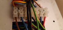
Right, try and identify and write down whats written on the boiler terminal block, especially referring to the burner.
The puzzling bit, to me, is that terminal 1 is the switched live from the MPV irrespective of what position its in but this voltage is rock steady (ter1 to N) in all three positions, which is indicitive of no MPV fault, however ter7 to N is a bit erratic with HW&CH on, its ( ter7 to N) steady in CH only but in HW only varies 6V to 180V, yet no problems with HW only on.
The puzzling bit, to me, is that terminal 1 is the switched live from the MPV irrespective of what position its in but this voltage is rock steady (ter1 to N) in all three positions, which is indicitive of no MPV fault, however ter7 to N is a bit erratic with HW&CH on, its ( ter7 to N) steady in CH only but in HW only varies 6V to 180V, yet no problems with HW only on.
1. Live
2. Neutral
3. Earth
4. Burner Lock out
5. Burner Earth
6. Burner Neutral
7. Burner Live
Just off out for a couple of hours. When back I'll have another look at diagram. For me its hard enough when everything is working normally.
2. Neutral
3. Earth
4. Burner Lock out
5. Burner Earth
6. Burner Neutral
7. Burner Live
Just off out for a couple of hours. When back I'll have another look at diagram. For me its hard enough when everything is working normally.
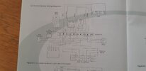
I think THIS is the correct one (it includes your boiler terminal block), you can forget about 4 to N crazy readings but two things you might do is with the boiler powerd up but neither HW or DHW on, test for voltage between 1 & N and 7 & N on the boiler terminal block, I wouldn't expect any reading on 1 to N (switched live) but would expect a steady 240V between 7 and N as this should be the boiler permanent live. Also with CH & HW on try and locate the wiring centre and test between 10 and 2,
Attachments
Last edited:
DIYnot Local
Staff member
If you need to find a tradesperson to get your job done, please try our local search below, or if you are doing it yourself you can find suppliers local to you.
Select the supplier or trade you require, enter your location to begin your search.
Please select a service and enter a location to continue...
Are you a trade or supplier? You can create your listing free at DIYnot Local
Sponsored Links
Similar threads
- Replies
- 10
- Views
- 3K
- Replies
- 3
- Views
- 476
- Replies
- 1
- Views
- 1K
- Replies
- 3
- Views
- 1K
- Replies
- 10
- Views
- 12K