You are using an out of date browser. It may not display this or other websites correctly.
You should upgrade or use an alternative browser.
You should upgrade or use an alternative browser.
Grant oil boiler hunting
- Thread starter George J
- Start date
Sponsored Links
Just confirm that I've got this right.
From post 26
HW+CH??
2(N) - 1 240v constant
2(N) - 4 all over the place. Probably about 58. is most consistent reading
2(N) - 7 240 through cycles. Shows OL for split sec when switching back on
From post 30
HW only?
2(N) - 1 240v constant
2(N) - 4 all over the place
2(N) - 7 random figures as low as 6v and up to 180v
I don't have a room stat just TRV on rads.
From post 31
CH only?
2(N) - 1 240v constant
2(N) - 4 all over the place
2(N) - 7 240v constant
Sponsored Links
Right, try and identify and write down whats written on the boiler terminal block, especially referring to the burner.
The puzzling bit, to me, is that terminal 1 is the switched live from the MPV irrespective of what position its in but this voltage is rock steady (ter1 to N) in all three positions, which is indicitive of no MPV fault, however ter7 to N is a bit erratic with HW&CH on, its ( ter7 to N) steady in CH only but in HW only varies 6V to 180V, yet no problems with HW only on.
The puzzling bit, to me, is that terminal 1 is the switched live from the MPV irrespective of what position its in but this voltage is rock steady (ter1 to N) in all three positions, which is indicitive of no MPV fault, however ter7 to N is a bit erratic with HW&CH on, its ( ter7 to N) steady in CH only but in HW only varies 6V to 180V, yet no problems with HW only on.
1. Live
2. Neutral
3. Earth
4. Burner Lock out
5. Burner Earth
6. Burner Neutral
7. Burner Live
Just off out for a couple of hours. When back I'll have another look at diagram. For me its hard enough when everything is working normally.
2. Neutral
3. Earth
4. Burner Lock out
5. Burner Earth
6. Burner Neutral
7. Burner Live
Just off out for a couple of hours. When back I'll have another look at diagram. For me its hard enough when everything is working normally.
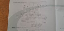
I think THIS is the correct one (it includes your boiler terminal block), you can forget about 4 to N crazy readings but two things you might do is with the boiler powerd up but neither HW or DHW on, test for voltage between 1 & N and 7 & N on the boiler terminal block, I wouldn't expect any reading on 1 to N (switched live) but would expect a steady 240V between 7 and N as this should be the boiler permanent live. Also with CH & HW on try and locate the wiring centre and test between 10 and 2,
Edit: Does your programmer have HW OFF position which switches 230V to terminal 7 in the wiring centre?.
Edit: Does your programmer have HW OFF position which switches 230V to terminal 7 in the wiring centre?.
Attachments
Last edited:
I haven't read all these comments but those Honeywell controllers are somewhat unreliable from my experience (and others!), for example, my 9100 went bad and the hot water was fine but central heating went intermittent and, amazingly, it was the Honeywell controller going bad.... I found a temp solution was to turn OFF the Honeywell's LCD backlight and this restored central heating, it sounds bizaare but is a known issue with these controllers. A replacement cured my issue and I repaired the old one with some new capacitors (not really worth the hassle). These controllers are made so cheaply that their power supply can go bad and when starting to fail it struggles to control one or both of the relays. Turning off the LCD backlight means the failing powersupply is slightly less under load and can then sometimes work for a bit longer...it's something worth checking out.
Other issues with my Grant combi 26 outdoor boiler (the worst, most unreliable boiler I've ever had) includes failing main PCB causing no hot water and required complete new PCB (£100 self replaced). Intermittently, the pump for CH inside the boiler went intermittent, tapping the 3 speed selector switch on the motor would make the motor spin due to the 3 position switch built into the pump failed due to plastic fatigue not pressing the switch together reliably (I soldered the switch to be at position 3 only and it's worked for 10 years fine).
Other issues with my Grant combi 26 outdoor boiler (the worst, most unreliable boiler I've ever had) includes failing main PCB causing no hot water and required complete new PCB (£100 self replaced). Intermittently, the pump for CH inside the boiler went intermittent, tapping the 3 speed selector switch on the motor would make the motor spin due to the 3 position switch built into the pump failed due to plastic fatigue not pressing the switch together reliably (I soldered the switch to be at position 3 only and it's worked for 10 years fine).
Last edited:
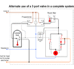
Very interesting, I think we are all inclined to blame the MPV since its such a devilishly cunning but ingenious device. a electrical friend of mine many moons ago modified his with a extra relay to make it return to the unpowerd state after any CH request, the MPV outlived him and is still going strong as far as I know. I came across a nice schematic fairly recently of how this might be done.
Attachments
boiler on but CH and DHW off
1 - N no V
7 - N no V
both give less that 0.01 Volts
(you are referring to terminal 2 Neutral and not terminal 6 Burner Neutral)
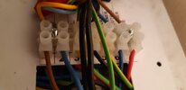
Can't find the wiring centre terminals. Are they in programmer ?
I just noticed that with CH on, boiler working OK, the cyl feed from MPV is supplying heat to cyl as well as rads. Which also means, as pump is working, volts are OK between wiring centre 2 and 10. Does this mean we can assume volts are OK ?
DIYnot Local
Staff member
If you need to find a tradesperson to get your job done, please try our local search below, or if you are doing it yourself you can find suppliers local to you.
Select the supplier or trade you require, enter your location to begin your search.
Please select a service and enter a location to continue...
Are you a trade or supplier? You can create your listing free at DIYnot Local
Sponsored Links
Similar threads
- Replies
- 10
- Views
- 3K
- Replies
- 3
- Views
- 577
- Replies
- 1
- Views
- 1K
- Replies
- 3
- Views
- 2K
- Replies
- 10
- Views
- 12K


