Ohms Law Quiz

Apart from ericmark no one answered was that too hard?
Regarding the simple ohms law questions I was going to go for different layouts rather than values, some people find it hard to visualise a circuit when components are differently orientated and can then get their answers wrong.
I'm just trying to find a happy medium for the forum, should i continue posting puzzles, people still interested?
 
Sponsored Links
Sorry missed a set of brackets I got it wrong.
At 50 Hz Current = 142.1031304ma and voltage = 4.523283127 volts
At 60Hz Current = 119.4963906ma and voltage = 3.169740207 volts
Since frequency was not given so here is a chart to show frez compared with both milliamp and voltage.
Frequency was 50Hz as shown bottom of diagram.
Very close with the answers but small error margin, didnt show the answers in degrees though ;)

want to give it another try eric or shall i post the answers?
 
You have not included any resistors in the problem. In real terms there would be a mixture of resistance capacitance and inductance. And yes once one adds some resistance one would also need to work out lead or lag in degrees. But this will be 90 deg lag.
Since no other answers and I note my problem got no answers either it seems know one wants to get involved in complex numbers.
This is a DIY forum and the book I was using to revise with was level 4 to 6 and using Argand diagrams and J notation is not really likely to be of much interest to most readers.
I did note with BAS example we had some wrong answers and it is so easy to make a error as I did missing out just one set of brackets.
Which means to publish the answer really needs the step by step workings to show any errors.
In another 24 hours if you get a few more answers it may be worth it but I am sure my method is correct and any error will be another set of missing brackets or some other minor error on the spread sheet and hardly worth your time and effort to write out the answer with workings and without workings it is hardly worth the effort as it would not really show where the error was.

I was rather surprised that Electronics Work Bench did not give a stable answer?
 
ericmark you are correct about the resisitance in the circuit, in my haste to put the problem out I drew the circuit and completely forgot about it having any form of resisitance :)

Thats said the circuit is still solvable and as it looks like there may not be any more answers forthcoming i'll show the solution

well done with your answers as its quite a complex solution.

View media item 8865
 
Sponsored Links
the current through the capacitor measured would lead the voltage by 90 degrees, but the current through the ammeter would be in phase ( 0 deg ) with the voltage due to the inductor correcting it..

so to answer your question..

the voltage at the voltmeter would be at 0 deg in relation to the supply voltage, and the current through the ammeter would be at 0 deg with relation to the supply current..
I got 4.53V and 0.142A
 
In a practical circuit not only is there resistance, but also the current has to be switched on. That will cause a transient and possible ringing at the resonant frequency of the circuit.

The j method is difficult. I would use laplace tranforms except it's years since I last did so and I don't want to wear my brain out finding out how to use them again. :eek:
 
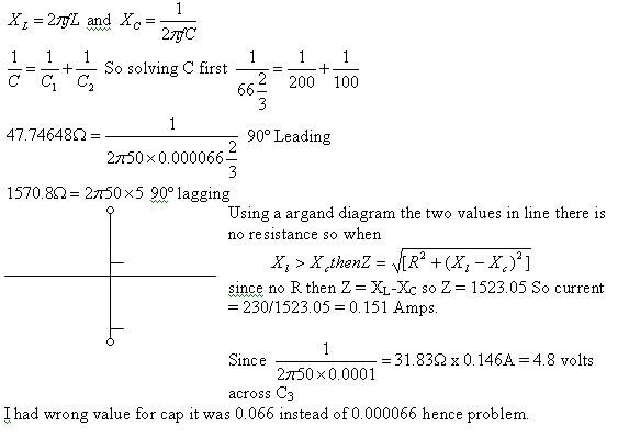
I am looking a lower case omega squared and can't see where that comes in as since no resistance the square and square roots cancel each other. And I see no square roots only squares? If you had included values as well as how calculated it may have been easier to find.
When I entered 1/2*pi()*50*0.0001 I also got wrong answer and had to enter 1/(2*pi()*50*0.0001) and I will guess it is something like that which has caused our answers to differ.
 
glad to see some remember their college work :)
perhaps I should make them simpler?
 
OK so what other than making band pass filters for the TV would I use it for?
We got all the "This is needed for power factor correction" when in University but on the one time I was involved with fitting a power factor correction unit it was raw bolted in and the cables were fitted and the guys from Siemens came with a PC and set it up.

A nice little window displayed what it was doing and from time to time we heard the contactors going in and out.

I did not see anyone setting it up do any calculations and the only way I know of measuring the power factor is with an oscilloscope.

So in real terms when will we ever use those calculations except with my hobby of being a radio ham?
 
I did not see anyone setting it up do any calculations and the only way I know of measuring the power factor is with an oscilloscope.
You could use a PF meter (I have a clamp on one - clicky - even does DC power factor :confused: ),
or from my college days, use a volt meter, current meter and a wattmeter.
 
Yes I know they exist but the big boxes of capacitors will often have a meter like this
Power_Factor_Meter.jpg
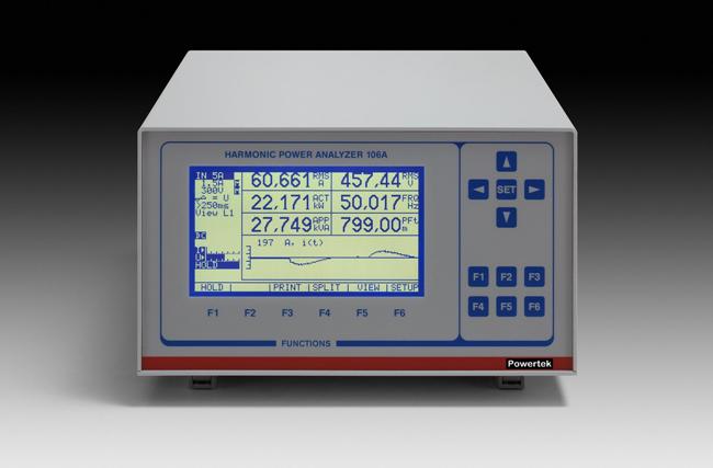
built in and you can get these
PA106front.jpg
and even these
resize_image.aspx
but non of these really need you to get the calculator out and really do some maths. Charts and tables will be used to select the correct value.

Of course it is the same for many more items. I think of the MCB's being B, C and D and that is 5, 10, and 20 times the stated current to trip so a 16C trip will need 160A to trip and ohms law 230/160 = 1.4375 but for those who can't work it out themselves page 49 on red book works it out for you at 1.44 ohms. Since the red book is a bit too big to carry in ones back pocket I find the calculated method very handy. But for those who can't do the maths there is always the Red book.

But I have never needed to use the Xl = 2pifL as an electrician. I have when doing my hobby and making filters but not as an electrician.

Neither have I ever used J the square root of -1. I did all these example in Uni but never needed to work it out in real life.
 
Good old j notation and imaginary numbers ;)
I'm about to do that on a course I am attending, in the real world I doubt I will ever need to use it.
For the MCB thing, you need to be able to know how to calculate it as the figures in the red book only refer to common voltages such as 230v and RLV.
 

DIYnot Local

Staff member

If you need to find a tradesperson to get your job done, please try our local search below, or if you are doing it yourself you can find suppliers local to you.

Select the supplier or trade you require, enter your location to begin your search.


Are you a trade or supplier? You can create your listing free at DIYnot Local

 
Sponsored Links
Back
Top