Relying on loads not being able to overload

I presume the Hager curves are correct for Hager devices; others probably different.

Perhaps that is why, for the problem being discussed, there are no standard charts and advice is given to contact the manufacturer's figures.


What text is associated with the IET curve chart you gave?

I suspect it is formed from the calculations.
 
Sponsored Links
Trying to calculate the let through energy of a circuit breaker operating on a magnetic trip using the fault level and your assumed disconnection time (the regs assume 0.1 sec but it might in practice be 0.01 or 0.03 or 0.04 etc) is likely to lead to nowhere...
Well, if (as I did for my tables) one uses the regs’ 0.1s figure, I would say that one gets somewhere - namely to an undoubtedly very conservative answer (which tends to be the case with most things reg-based). However, I suppose I should have realised that someone would jump in, sooner or later, and suggest that I should be assuming a much smaller (they would say ‘more correct’) disconnection time.
What you need to do is consult either the manufacturers data if available or the generic I²t data in BSEN60898 which will give you the I²t at various fault levels.
I’m not sure I understand the difference between that and seeing sufficiently detailed (and complete) t/I curves.
Remember that you must consider the most onerous condition, so obtain I²t for a fault occurring at the board and at furthest point.
In the context of this thread (if anyone can remember what it’s mean to be about :) ), we were, at least by implication, considering a situation in which a circuit had a more than adequate CPC for most of its length, but with a considerably reduced csa for the ‘final bit’, with a fault at the end of that reduced-csa cable.
For a thermal device, (such as a fuse) the worst case is far end as the I²t to blow it (remember this is directly proportional to enegry) remains more or less constant, however at lower currents some of it transfers into the environment (think of a 240v kettle on 110v, it'll still put thermal energy into the water but it probably wont ever boil even after an hour).
Sure, we tend to think of fuses behaving adiabatically, but that ceases to be true if the over-current is so modest that the fuse doesn't operate within a small number of seconds.

Kind Regards, John
 
I presume the Hager curves are correct for Hager devices; others probably different. Perhaps that is why, for the problem being discussed, there are no standard charts and advice is given to contact the manufacturer's figures.
I rather doubt that they are Hager-specific. Although I don't have access to verify it, I think they are very probably BS EN 60898 curves. If they were empirically-derived curves based on their own devices, it's almost inconceivable that they would get exactly the range of Ia values that is required by the Standard (e.g. 3*In - 5*In for Type Bs)
What text is associated with the IET curve chart you gave? I suspect it is formed from the calculations.
No, the text is unhelpful. The graph exists in the context of illustrating the graphical (rather than calculation) method of examining CPC adiabatics - with the 'conductor adiabatic curves' (the dotted straight lines) superimposed on the "operating characteristics of a Type D MCB".

I'm going to have a look around and see what other MCB curves I can find.

Kind Regards, John
 
The way I see it is this:-

For MCB providing fault protection only, extra calculations are necessary. I take it it that (please correct me if wrong) in the disconnection interval where the time is stated to be 'instantaneous' for an MCB (I take this (or had) as between 0.1 second and 5 seconds) the adiabatic equation is used. Below this time then, as Adam says, energy let through calculations are done using data from the MCB manufacturers. Aside from John's very interesting subject matter (but which is closely related and hence raised) is the recommendation by Coates and Jenkins, in their fourth edition, that the minimum disconnection time of 0.01 seconds is used in the adiabtaic equation to give the formula 0.1Uo/kS as the minimum impedance at the MCB to protect the CPC, resulting in a far more useable range of Ze & R1+R2 combinations than would be implied by the figures shown in 'John's' table. So I am seeking to clarify that without hijacking John's thread, as it seems to me there is some confusion about it.

I have asked in the other place and will report my findings, even if these do expose my ignorance.

Regards
 
Sponsored Links
I'm going to have a look around and see what other MCB curves I can find.
Well, I don't know :) ...

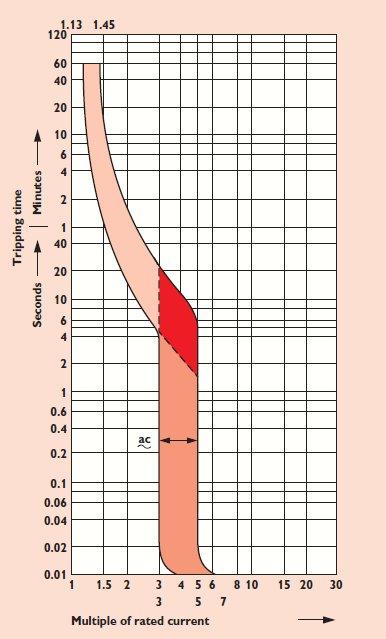
This one from Wylex looks very similar, certainly 'down the bottom', to the Hager ones (goodness only knows what the "ac~" is all about!):
... but what about this one, from the same page of Wylex!!....
... and this offering from MK ...
I cannot help by wonder whether the latter two are to some extent theoretical/hypothetical, since they appear to be showing curves going down to disconnection times which I would have thought were less than any ('cheap') physical mechanism could achieve.

Kind Regards, John
 
The way I see it is this:- For MCB providing fault protection only, extra calculations are necessary. I take it it that (please correct me if wrong) in the disconnection interval where the time is stated to be 'instantaneous' for an MCB (I take this (or had) as between 0.1 second and 5 seconds) the adiabatic equation is used. Below this time then, as Adam says, energy let through calculations are done using data from the MCB manufacturers.
I discussed this before. Above about 5 seconds, the process is not adiabatic, so no adiabatic approach is appropriate/acceptable. For very short disconnection times (and certainly if less than half a cycle) an adiabatic approach is very appropriate, but one cannot use the normal simple equation (as per regs), since using RMS current will not give a correct measure of I²t - one has to integrate I² over t for the part of the waveform in question to get a proper value for I²t.
Aside from John's very interesting subject matter (but which is closely related and hence raised) is the recommendation by Coates and Jenkins, in their fourth edition, that the minimum disconnection time of 0.01 seconds is used in the adiabtaic equation to give the formula 0.1Uo/kS as the minimum impedance at the MCB to protect the CPC, resulting in a far more useable range of Ze & R1+R2 combinations than would be implied by the figures shown in 'John's' table. So I am seeking to clarify that without hijacking John's thread, as it seems to me there is some confusion about it.
Indeed. I think we are now all agreed that using 0.1 seconds is probably over-conservative (which is perhaps why the IET use it in the regs and other publications, so as to require the minimum of thought or knowledge in its application!). I suspect, however, that you will get a range of 'expert opinions'.

Kind Regards, John
 
John,

Although it can be inferred from the way I have written my last reply that I believe that the adiabatic only applies between 0.1s & 5s you will know from all my previous arguments that this cannot be what i mean. I have used the adiabatic and confirmed the derivation of Coates and Jenkins formula they advocate to be used at 0.01s. What i should have said is that below 0.1s conventional wisdom would appear to advocate using energy let through data.

Regards
 
What i should have said is that below 0.1s conventional wisdom would appear to advocate using energy let through data.
Fair enough, but, as you understand, you'll still be undertaking an adiabatic calculation once you have your value of I²t, wherever it comes from and whatever you call it.

I'm certainly very much open to education, but I imagine that, in determining the I²t (whether one calls it 'energy let through' or anything else) when t is small (less than 'a few cycles') and not exactly equal to a whole number of half cycles (and certainly if it is less than one half cycle), one has to use either the 'largest possible' or 'smallest possible' value of I²t (given that it will presumably vary according to what point in a cycle the fault starts), according to whether, in one's application, a smaller or larger I²t would be the 'more conservative'. Is that correct?

Kind Regards, John
 
Hi

You need to assess the fault current levels, front end and far end. Then you will either have a disconnection time or a I2t to use within the adiabatic.

cheers
chris
 
John,

You'll have go ask much higher authorities than me. I have read that, below 0.01 seconds, the energy transfer is considered to be non-adiabatic. That is, heat is involved due to the fact that a plasma field develops. Cannot remember where I saw it and do not know whether itsis correct but is one of the sets of data that I am lining up (if true) to include in a logical design sequence.

Regards
 
John, You'll have go ask much higher authorities than me. I have read that, below 0.01 seconds, the energy transfer is considered to be non-adiabatic. That is, heat is involved due to the fact that a plasma field develops.
Goodness, that's an intriguing suggestion! However, it doesn't really make much sense to me in relation to what we're talking about. We are, after all, talking about calculations to determine whether or not a CPC is 'adequately protected' under fault conditions - and I find it extremely hard to believe that it would be considered to have been 'adequately protected' if it got so hot as to result in plasma formation! ...but maybe were talking about things and phenomena which go way above my head!

Are you sure you're not talking about what happens in the MCB (rather than the circuit's CPC) when the MCB it breaks a high fault current? - I can well imagine that arcing can produce plasma there.

Kind Regards, John
 
The adiabatic assumes all heat is contained within the conductor, this is relatively true for disconnection times upto 5 secs , upto ten seconds with certain cable sizes if memory serves me right. Beyond these times we have no adiabatic, now heat is lost into surrounding insulation, if we use the adiabatic in these instances it will err on the side of caution.

Cheers
chris
 
The adiabatic assumes all heat is contained within the conductor, this is relatively true for disconnection times upto 5 secs , upto ten seconds with certain cable sizes if memory serves me right. Beyond these times we have no adiabatic, now heat is lost into surrounding insulation, if we use the adiabatic in these instances it will err on the side of caution.
Yes, I've said all that, and I think everyone agrees that the process ceases to be adiabatic with disconnection times beyond a few seconds (as you say, 5 sec or so being the usual 'limit'). If current flows for a very long time, one obviously ends up with the antithesis of an adiabatic process, namely a thermal steady state.

However, what THRIPSTER has suggested is that the process ceases to be adiabatic with disconnection times less than 0.01 sec. That clearly is far too little time for any significant amount of heat to be lost from the conductor by any of the usual heat transfer processes - but I just don't know what to think or say about his suggestion that heat may be lost via a 'plasma field' - which, for the reasons I gave (and others), sounds extremely far-fetched to me!!

Kind Regards, John
 
With disconection times less than 0.01 you need to refer to the manufacturers A2S/I2t, where large fault current exist, these figures are derived through test and measurement, though its still definitely an adiabatic process.

cheers
chris
 
Of course the suggested plasma forms within the MCB!

I am getting the distinct impression that I should not continue here.

Goodbye
 

DIYnot Local

Staff member

If you need to find a tradesperson to get your job done, please try our local search below, or if you are doing it yourself you can find suppliers local to you.

Select the supplier or trade you require, enter your location to begin your search.


Are you a trade or supplier? You can create your listing free at DIYnot Local

 
Sponsored Links
Back
Top