Sub main query

I think you could probably use the adiabatic equation to work out the maximum CCC of XLPE conductors at 70°C if you really wanted to.
You could probably work it out, but not with the adiabatic equation.(The adiabatic assumes no heat is lost to the surroundings, which is an approximation which gives a reasonable result up to about 5 seconds)
Quite so - as I wrote last night...
That approach would be inappropriate. CCC is all about a thermal steady state during continuous current flow - which is the antithesis of an adiabatic process. An adiabatic calculation would only tell you what (very high) current the conductor could tolerate for a very short period of time (usually taken as <5s) - and that current would be many times greater than the 'CCC' of the conductor.
As you say, one could probably work it out by some other means, but I suspect that it would require knowledge of characteristics/properties of the cable and its insulation which mere mortals like you, I and RF probably don't have! For example, I presume that the presence of the armour has an appreciable bearing on the thermal behaviour of SWA.

Kind Regards, John
 
Sponsored Links
So apparently the studio is really a new build house, the PME supply is a temporary TT one, all the advice given on that other forum was totally ignored, and it's anyone's guess as to what shambles has been made of the wiring in the house.
 
Sponsored Links
In the mirror?

Nah - I think that's his impression (that I don't share) of the people on here who have spent their valuable time trying to help him.

However, I agree that he would be far more likely to attain his degree in proctology by looking in the mirror.
 
So apparently the studio is really a new build house, the PME supply is a temporary TT one, all the advice given on that other forum was totally ignored, and it's anyone's guess as to what shambles has been made of the wiring in the house.
He's going to have fun getting his Building Regulations completion certificate. It won't take much going around the loop on that before he is waaaay out of pocket compared to what it would have cost him to employ someone competent. Even more so if he's adopted the same cavalier approach of incompetence-is-no-bar-to-DIY with the structure.
 
Ah - you're back.

What are you now going to do about Building Regulations sign-off?
 
I am providing a new sub-main to a new studio/workshop which is about 30m away from a garage CU. I have run the cable through underground ducting and already backfilled the trench. The cable is 16mm 3C SWA.
My guess ...
Someone was in a hurry, just looked up the CCC of a piece of cable and dropped that in the trench - before they'd done the full design.

OK, while I fully agree that the OP is out of his depth - big time - hands up anyone who's never had an "oops, should have thought that through a bit more" moment ?

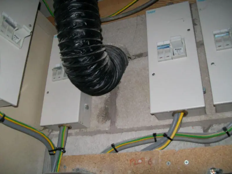
FWIW, I'd agree that it makes more sense to split the tails and use a separate switch fuse. Apart from the issues of taking another 16mm cable into the CU (space, the mechanical load it'll put on what can be quite flimsy internals, etc) - it means the garage supply can be turned off if needed (eg for maintenance) without affecting the "studio". Overall, it needn't look too bad - these are the supply ends of the submains to the flats of which I own one - these are done with 16mm T&E, but SWA could easily be terminated directly into the switch.

If the cable is in a duct, can it be pulled out and replaced without opening the trench ? I can see that it might be necessary to dig a hole at each end to remove the bends and give a straight pull, but it ought to be possible unless the duct is far too small.


PS - I too am curious as to what loads are involved, why the OP would be out of a job if this cock-up comes to light, and what his real job is - just guessing that the 2nd and 3rd of those questions are related :rolleyes:
 
Good morning!

Hoping to get some advice from someone more knowledgeable and experienced than I am.

I have a 100A PME supply to a garage.

I am providing a new sub-main to a new studio/workshop which is about 30m away from a garage CU. I have run the cable through underground ducting and already backfilled the trench. The cable is 16mm 3C SWA.

The plan was to EITHER split the meter tails and provide an independent supply via an 80A switch fuse OR fit an 80A MCCB to a spare way in the existing garage CU. The studio will have a 100A DP isolating switch with all circuits protected by RCBOs.

The SWA cable has a maximum rating of 91A and I designed the installation on this basis. I realise now that the cable won't be able to take this load in practice and I think I will have to downgrade the design load from 80A to say 63A.

Needless to say I'd rather not do this unless it is strictly necessary since it will invite all sorts of difficult questions!

Like I said, I'd be very grateful for some definitive advice as to what load the existing 16mm SWA cable can safely take.

Regards

J

Cross posted on the IET forum also? :D
 

DIYnot Local

Staff member

If you need to find a tradesperson to get your job done, please try our local search below, or if you are doing it yourself you can find suppliers local to you.

Select the supplier or trade you require, enter your location to begin your search.


Are you a trade or supplier? You can create your listing free at DIYnot Local

 
Sponsored Links
Back
Top