
You are using an out of date browser. It may not display this or other websites correctly.
You should upgrade or use an alternative browser.
You should upgrade or use an alternative browser.
Texecom JAL-0001 ComPort+ Digi Modem Port Pinout?
- Thread starter texecom
- Start date

Sponsored Links
ive raised a topic with the dev of stream server is debug logs look little funny:It is very frustrating and I can't explain it because it should just work...
This is why I went down the Pi route to reduce my blood pressure!
Component uart took a long time for an operation · Issue #54 · oxan/esphome-stream-server
Hi, My config flashes perfectly and ive enabled debug, here is my code: esphome: name: texecom-link friendly_name: texecom-link esp8266: board: d1 external_components: - source: github://oxan/espho...
 github.com
Looking at the logs, I suspect that although it states you connected, it probably never fully established a connection at all and the software is just timing out which is identical to my issue.
Maybe the author got lucky with his ESP module and it just works and our boards are using cloned chipsets or something and just don't work with the Texecom hardware.
I may grab a few totally different types of ESP8266 modules myself and get to the bottom of it.
Maybe the author got lucky with his ESP module and it just works and our boards are using cloned chipsets or something and just don't work with the Texecom hardware.
I may grab a few totally different types of ESP8266 modules myself and get to the bottom of it.
Sponsored Links
Happy to throw some £ your way for hardware as I hate not getting to the bottom of thisLooking at the logs, I suspect that although it states you connected, it probably never fully established a connection at all and the software is just timing out which is identical to my issue.
Maybe the author got lucky with his ESP module and it just works and our boards are using cloned chipsets or something and just don't work with the Texecom hardware.
I may grab a few totally different types of ESP8266 modules myself and get to the bottom of it.
Edit, just to add, ive tried multiple boards, with and without the LLC, different pins you name it.
I'll keep that issue linked above active as hopefully gets the developer having a look too.
Last edited:
Had another play around with my ESP8266 modules earlier and had them talking to each other and also a RPi through PuTTY with and without the level convertor with no problems at all.
Still puzzled, I came across a post online that basically said:
"The problem with the Rx pin on D1 Mini is that it is connected to the USB/UART converter chip.
So you would hope it is high impedance and can easily be driven - but you are really seeing the impedance of the USB chip output pin.
A real WEMOS D1 mini has a 500 ohm resistor in series so you can overdrive that output, but many of the clones omit this series resistor, making the Rx pin unusable."
Last edited:
So success after some more testing...
I separated the RX and TX lines to see if it was one or the other that was causing the issue on the ESP modules.
I set up the panel so that so that the ESP module was sending data to the panel and the Pi was receiving from the panel and everything worked!
When I send data to the panel from the Pi and try to receive data from the panel through the ESP module nothing is detected.
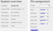
Fortunately, in ESP-Link you can swap the TXD & RXD pins to GPIO 13 & 15 (written on the back of the PCB) and as soon as I did this and set the baud rates up everything worked perfectly and actually quicker than the Pi!!!
I have fully tested this using Wintex & Crestron and it works - in fact you can leave the COM3 setting on Crestron all the time and it works on both. Wintex when connected and then defaults back to Crestron
I suspect you can do the same in ESP Home?
There are a couple of caveats:
1 - The level convertor must still be used because the D1 3.3v TX voltage level is simply not high enough for the panel to read properly. The D1 RX from the panel is OK but you may as well use both channels in the level convertor as a failsafe.
2 - When GPIO15 is pulled high (by being connected to the panel) the D1 will not boot and therefore must be unplugged briefly at power on. This will not really be an issue because it will run off the panel and be powered all the time so should never need to reboot but it could be an annoyance. There is probably a work around for this.
I separated the RX and TX lines to see if it was one or the other that was causing the issue on the ESP modules.
I set up the panel so that so that the ESP module was sending data to the panel and the Pi was receiving from the panel and everything worked!
When I send data to the panel from the Pi and try to receive data from the panel through the ESP module nothing is detected.
Fortunately, in ESP-Link you can swap the TXD & RXD pins to GPIO 13 & 15 (written on the back of the PCB) and as soon as I did this and set the baud rates up everything worked perfectly and actually quicker than the Pi!!!
I have fully tested this using Wintex & Crestron and it works - in fact you can leave the COM3 setting on Crestron all the time and it works on both. Wintex when connected and then defaults back to Crestron
I suspect you can do the same in ESP Home?
There are a couple of caveats:
1 - The level convertor must still be used because the D1 3.3v TX voltage level is simply not high enough for the panel to read properly. The D1 RX from the panel is OK but you may as well use both channels in the level convertor as a failsafe.
2 - When GPIO15 is pulled high (by being connected to the panel) the D1 will not boot and therefore must be unplugged briefly at power on. This will not really be an issue because it will run off the panel and be powered all the time so should never need to reboot but it could be an annoyance. There is probably a work around for this.
Last edited:
oh wow I didn’t expect to see a message like this so soon!
Congrats, I can’t tell you the stress this has caused me
I think I have the same wemos D1 esp8266 clone board as you. If I’m reading right you didn’t need to add any new hardware you simply changed your GPIO pins from 01 and 03 to 13 and 15? Can you send some photos of your setup (and the LLC) and your esp-link config so I can try replicate. Then I’ll try again with esphome.
Thank
I can finally get some sleep
Last edited:
After looking at the circuit diagram, I have found a way to make the normal RX pin useable and it involves removing a resistor. Basically this disconnects the USB chip from the RX input and means that the ESP8266 on the D1 works!
BUT you need to make sure you have written the software to the ESP8266 first otherwise you can no longer write to it unless you replace the resistor!!!
The easiest way to write the ESP-Link to the D1 is using this link:
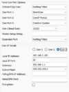
This installs an older version of ESP link but it does the job, configure it with your own wifi settings etc. and identical to these images:


And then unplug it and remove the resistor:
This is the circuit diagram:

and this is the position on the board of the 470 ohm resistors, you only need to remove the RX one circled but I removed both.

Once you have done this, connect up to the panel via the level convertor the same as you did for the RPi with 3.3v to the LV and 5v to the HV and providing your panel COM3 is still set to Crestron you can telnet through PuTTy to the IP on port 23 and enter Crestron commands or you can connect using Wintex, again to the IP on port 23 and play all day.
You will find that if you switch between Crestron and Wintex there is a slight delay on the COM port which I suspect is the panel timing out between the protocols and I don't know why both Crestron and Wintex work with the 8N2 setting but they do...
As a side note, both Wintex and Crestron work with the 8N1 setting as well. Interestingly, if you use 8E1, Wintex connects first time but Crestron will not communicate.
BUT you need to make sure you have written the software to the ESP8266 first otherwise you can no longer write to it unless you replace the resistor!!!
The easiest way to write the ESP-Link to the D1 is using this link:
Install ESPLink
aceindy.github.io
This installs an older version of ESP link but it does the job, configure it with your own wifi settings etc. and identical to these images:
And then unplug it and remove the resistor:
This is the circuit diagram:
and this is the position on the board of the 470 ohm resistors, you only need to remove the RX one circled but I removed both.
Once you have done this, connect up to the panel via the level convertor the same as you did for the RPi with 3.3v to the LV and 5v to the HV and providing your panel COM3 is still set to Crestron you can telnet through PuTTy to the IP on port 23 and enter Crestron commands or you can connect using Wintex, again to the IP on port 23 and play all day.
You will find that if you switch between Crestron and Wintex there is a slight delay on the COM port which I suspect is the panel timing out between the protocols and I don't know why both Crestron and Wintex work with the 8N2 setting but they do...
As a side note, both Wintex and Crestron work with the 8N1 setting as well. Interestingly, if you use 8E1, Wintex connects first time but Crestron will not communicate.
Last edited:
so ive flashed ESPlink, setup as you've done and it connects to my wifi, removed the resistor (well left it half attached). Connected via 12v everything boots but I can't send any commands. Checked wintex Is set as port 23 and the esp link IP
Can you send a photo of how you've connected it to your ESP please?
To confirm, your using GPIO D2 and GPIO14 as your pins as marked?
Can you send a photo of how you've connected it to your ESP please?
To confirm, your using GPIO D2 and GPIO14 as your pins as marked?
Attachments
Last edited:
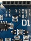
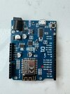
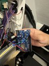
Your wiring all looks OK but you need to move the blue and red TX/RX leads to D0 & D1 as per this picture and it should work:

You'll see I am powering my board over USB at the moment and I have left my LLC cable tied to my Pi but it is running totally from the D1.
I see that your board has 220 ohm resistors where mine has 470ohm but they were probably cheaper at the time!
I would also remove the Com-IP details you have put in Wintex because it serves no purpose and may conflict:

This is the important part to put the IP and port info:

You'll see I am powering my board over USB at the moment and I have left my LLC cable tied to my Pi but it is running totally from the D1.
I see that your board has 220 ohm resistors where mine has 470ohm but they were probably cheaper at the time!
I would also remove the Com-IP details you have put in Wintex because it serves no purpose and may conflict:
This is the important part to put the IP and port info:
Last edited:
hmmm done exactly as you have, still doesn't connect.
Ive also completely redone fresh with a new LLC and all new terminals. No commands being sent.
I thought first if I move the 5v around to lower down as I (thought) the 5v on the top side was for input and your LLC is powered via the Pi / something else. but still nothing.
Should I remove both resistors to see if thats it? (Also conscious you reference a d1 mini wiring diagram but this is a D1 R2)
Where did you get your ESP, as mine was from Amazon so a cheaper clone, lost for ideas (tried switching TX/RX too)

Ive also completely redone fresh with a new LLC and all new terminals. No commands being sent.
I thought first if I move the 5v around to lower down as I (thought) the 5v on the top side was for input and your LLC is powered via the Pi / something else. but still nothing.
Should I remove both resistors to see if thats it? (Also conscious you reference a d1 mini wiring diagram but this is a D1 R2)
Where did you get your ESP, as mine was from Amazon so a cheaper clone, lost for ideas
(tried switching TX/RX too)
Last edited:
You could remove the other resistor and try - it should not matter but it would isolate the TX line from the USB chip as well.
Try swapping the RX and TX leads because it is easy to mix them up!
Another test you can do to make sure your wiring and software are working correctly is simply connect the TX and RX pins coming from the D1, the easiest way is to unplug the 2 leads from the panel and put a Dupont lead between them. Then telnet through putty to the IP and port 23 and whenever you type a character you should see the echo back on screen. This will test all the way through the hardware up to the point it reaches the panel on both TX & RX.
Are the LEDs on the D1 working - you should have 1 on permanently, 1 as a heartbeat flashing every second or so and then the LED on the actual ESP8266 chip flash whenever data is sent or received?
I can't remember where I got my boards from because it was a while back but your boards looks almost the same so I would not get another just yet - it is more than likely something simple with the wiring or the GPIO inputs have been killed during the setup but the tests above should identify this.
Last edited:
removed the other resistor, no change. Tried also with removing the LLC entirely also no change.
LEDs wise, I have the ON led also list and occasionally a flashing SCK led, the ESP itself flashes whenever I try to send a command so looks good.
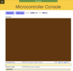
If I connect both the TX and RX pins together and connect via putty I can see the commands being sent and received (see screenshot). Though strange symbols show up if I send via putty (and view in esp-link you can see the text characters between the symbols)


I guess this suggests then the texecom panel is playing up? Ive checked everything and all looks good
I wonder if ive fried anything from playing around

MAJOR EDIT!
its the LLC, no matter how many different 4channel LLCs I use they don't work, the second I use a different 8 channel one everything works!!!
LEDs wise, I have the ON led also list and occasionally a flashing SCK led, the ESP itself flashes whenever I try to send a command so looks good.
If I connect both the TX and RX pins together and connect via putty I can see the commands being sent and received (see screenshot). Though strange symbols show up if I send via putty (and view in esp-link you can see the text characters between the symbols)
I guess this suggests then the texecom panel is playing up? Ive checked everything and all looks good
I wonder if ive fried anything from playing around
MAJOR EDIT!
its the LLC, no matter how many different 4channel LLCs I use they don't work, the second I use a different 8 channel one everything works!!!
Last edited:
It is unlikely you have damaged the panel unless you have connected more than 5v directly to the TX/RX pins.
The reason there is the strange spacing is probably because of the parity/spacing settings but don't worry about that atm, so let me get this right, just using putty, with the TX & RX connected, if you type something it is echoed back on screen yes? and if you disconnect TX & RX this does not happen yes?
If so then the wiring and software seems to be working...
From this picture, you have the TX and RX round the wrong way at the panel, the red and blue wire need to be swapped around - I have just double checked mine.
Once you have swapped the TX/RX pins telnet in to putty IP & port 23 and type ASTATUS and you should get this response:

You can also try changing to 8N1 on the ESP microcontroller screen to see if it helps?
In fact you don't have to type any commands at all, as long as Crestron is setup on COM3, as soon as an event is triggered, the panel will push a response to putty:

The reason there is the strange spacing is probably because of the parity/spacing settings but don't worry about that atm, so let me get this right, just using putty, with the TX & RX connected, if you type something it is echoed back on screen yes? and if you disconnect TX & RX this does not happen yes?
If so then the wiring and software seems to be working...
From this picture, you have the TX and RX round the wrong way at the panel, the red and blue wire need to be swapped around - I have just double checked mine.
Once you have swapped the TX/RX pins telnet in to putty IP & port 23 and type ASTATUS and you should get this response:
You can also try changing to 8N1 on the ESP microcontroller screen to see if it helps?
In fact you don't have to type any commands at all, as long as Crestron is setup on COM3, as soon as an event is triggered, the panel will push a response to putty:
DIYnot Local
Staff member
If you need to find a tradesperson to get your job done, please try our local search below, or if you are doing it yourself you can find suppliers local to you.
Select the supplier or trade you require, enter your location to begin your search.
Please select a service and enter a location to continue...
Are you a trade or supplier? You can create your listing free at DIYnot Local
Sponsored Links
Similar threads
- Replies
- 3
- Views
- 188
- Replies
- 9
- Views
- 2K
- Replies
- 19
- Views
- 3K