Texecom JAL-0001 ComPort+ Digi Modem Port Pinout?

Sure, I just knocked up a diagram to help...

Capture.JPG


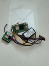
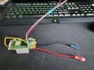
With the level shifter you are only shifting the TXD and RXD lines from the 3.3v that the Pi wants to 5v that the panel wants.

You can see from this the 5 wires going to the Pi and 3 wires going to the panel - excluding the DCDC module (you may want to test this without the module and just use a separate power supply until it is up and running)

You will notice TXD & RXD between the panel and Pi are swapped which is confusing but makes perfect sense.

The TXD & RXD from the Pi are connected to the LV side of the level shifter and then taken them from the HV side to the panel. You will also have GND connected from the Pi to the board and then on to the panel (this is basically a straight through connection) and also 3.3v from the Pi to the LV side and 5v from the Pi to the HV side of the level shifter PCB so that it has the reference voltages.

If you look at the pinout of the Pi a few posts back this should make more sense.

Does this help you understand the theory?
 
Sponsored Links
I'm not going to be around for a few days so I will just copy the text from my install notes below which should help you get up and running with the software side.

They are just my own dirty notes which are clear to me but probably a mess to everyone else so if you need any more clarification on anything come back and I'll reply when I can and do a full write up in due course:

***Note is a full command line install through PuTTY***

***You may/will need to play around with the YAML file config depending on what you are doing - best way to test is as is with Wintex***

---
RPi Build 2024-08-17 on RPi20W

Raspberry Pi Imager v1.8.5
Raspberry PI OS (64-BIT) LITE Bookworm
Options
>Set Hostname
>Set Password
>Set Wifi
>Enable SSH

Edit /boot/config.txt
[all]
enable_uart=1
dtoverlay=disable-bt
# Pi02W (Working)
# Turn off LED
dtparam=act_led_trigger=none
dtparam=act_led_activelow=on

IPScan for IP address if required

Boot RPi & SSH via PuTTY
>pi
>raspberry - unless changed
>sudo raspi-config
>3/6/No/Yes to enable Serial Port
Stay in PuTTY and Edit swapfile
>sudo nano /etc/dphys-swapfile
>Change CONF_SWAPSIZE=100 to 512
>sudo reboot now

#Using Nano create texecom.sh file in /home/pi and set permissions
>sudo nano /home/pi/texecom.sh
___
#!/bin/bash

sleep 5
sudo systemctl disable hciuart.service
sleep 5
sudo systemctl restart ser2net
___

#Make the script executable
>sudo chmod +x /home/pi/texecom.sh

sudo apt-get update
sudo apt-get upgrade

Install ser2net
>sudo apt install ser2net

Edit YAML file
>sudo nano /etc/ser2net.yaml
%YAML 1.1
---
# Find detailed documentation in ser2net.yaml(5)
# A fully featured configuration file is in
# /usr/share/doc/ser2net/examples/ser2net.yaml.gz

define: &banner \nOK \p \d

connection: &con001
accepter: tcp,10001
enable: on
options:
banner: *banner
kickolduser: true
# connector: serialdev,/dev/ttyUSB0,19200n82,local
connector: serialdev,/dev/serial0,19200n82,local

Create crontab for root from user prompt
>sudo crontab -e (sudo crontab -l to list tasks)
@reboot /home/pi/texecom.sh

sudo apt-get update
sudo apt-get upgrade
sudo reboot now

REBOOT AND BENCHTEST
 
I’ve soldered everything up and checked everything over, just can’t work out where you’ve attached the 12v power on the rail (Texecom main board), can you highlight it please?

Or are you using the 12v from the battery?
 

Attachments

  • image.jpg
    image.jpg
    230.8 KB · Views: 12
  • IMG_5524.jpeg
    IMG_5524.jpeg
    408.2 KB · Views: 18
*** DO NOT CONNECT THIS***

You have got the Pi round the wrong way 180 degrees, the pin that has the square mark is pin 1 - top right in your picture!!!
 
Sponsored Links
I can't see the writing on your PCB but I strongly suspect this is the Aux 12v connection where you should connect to?


Capture.JPG
 
LUCKILY i spotted as i was about to connect to the board, the image you posted above with the pin out I guess was the Pi 4 or 3 so I’ve switched it all around.
Whilst I wait for my case ive just stuck it in foam to protect shorts
Got it all connected up and it boots, now to install and report back ( bottom right corner is the pi)

#Edit, managed to install and configure everything as per your script (I did manually as running via Mac terminal). Also changed 'connector: serialdev,/dev/serial0,19200n81,local' like you said on previous page but for whatever reason I can't connect.

192.168.2.157 is my pi zero 2w, ive configured comport3 from wintex
Did you have to enable comport3 in ARCs? (like screenshot)

How did you test creston worked so I can try work out if ive done something wrong?
 

Attachments

  • IMG_5526.jpeg
    IMG_5526.jpeg
    286.3 KB · Views: 23
  • IMG_5528.jpeg
    IMG_5528.jpeg
    1.5 MB · Views: 21
  • Screenshot 2024-09-06 at 4.28.13 PM.png
    Screenshot 2024-09-06 at 4.28.13 PM.png
    49.7 KB · Views: 16
  • Screenshot 2024-09-06 at 4.34.03 PM.png
    Screenshot 2024-09-06 at 4.34.03 PM.png
    43 KB · Views: 14
  • Untitled.png
    Untitled.png
    52 KB · Views: 22
  • Screenshot 2024-09-06 at 6.59.09 PM.png
    Screenshot 2024-09-06 at 6.59.09 PM.png
    245 KB · Views: 16
Last edited:
It looks like you are making good progress!

To test the Crestron I put COM3 on Crestron and connected to the panel using PuTTY and then the panel pushes the data out over the connection.

In PuTTY (or your chosen terminal) connect to port 10001 on 192.168.2.157 and see if you get any response.

On connection you should get the top line OK tcp.......

Then type ASTATUS and the panel should respond with the areas that are armed or not as below:

Capture.JPG


Obviously my IP is different but if you see a response like this in PuTTy then then it is probably working.

If not, you can perform a loop back test by simply disconnecting the TXD & RXD leads going to the panel and joining them together and see if you can echo characters back in PuTTy.
 
Last edited:
Hmmm tried putty on windows and on mac still getting connection refused, I can SSH as pi ok though.

Any thoughts? Soldering looks good and all clean connections. Any other way to test hardware is working correctly rather than something in the YAML?

Does my config look good?
 
What response do you get when you try to connect in PuTTy to port 10001 on 192.168.2.157 as below?

Capture.JPG
 
"Network Error: Connection refused"
I assume this is my ser2net not correctly installed?
 

Attachments

  • Untitled.png
    Untitled.png
    125.1 KB · Views: 9
OK, so ser2net is not working correctly.

SSH in to the Pi and restart ser2net because you need to restart the service after any changes to the YAML file:

sudo /etc/init.d/ser2net restart

Then try again to connect in PuTTy to port 10001 on 192.168.2.157

You need to see this response (ignore IP and 19200n82 - yours will be 19200n81) before you look at the panel:

Capture.JPG
 
Looking at your YAML file I think it is wrong.

This is how it should look - nothing more and nothing less and make sure the lines are exactly as this because ser2net does not like spacing and line breaks so keep it nice and simple. You can just copy/paste the whole lot from my notes:

Capture.JPG


You will see I have commented out the 19200n81 line and this way I can quickly edit the file depending on what I want to do - the ttyUSB is if you want to use with a USBTTL adapter which also works but remember to restart ser2net after any changes.

Also, the cron job that is created from my notes and runs on boot disables the bluetooth uart service that automatically starts when the pi start and then restarts ser2net, again this is an important step otherwise ser2net will not work correctly.
 
Last edited:
you were right, it was my YAML - not sure how it got messed up.
tested everything and FULLY working. You’ve cracked it!!

Congrats!
All working with my homebridge and home assistant plugins
 
Hi guys, stumbled across this thread, I've been down a similar road, but I didn't use the level converter should I add one? I just went straight from the Pi Zero 2 to the Alarm, no issues as yet. Other than my Pi keeps locking up after a week or so, most likely due to a problem with my code. But I have it doing everything I want, I can Arm the Alarm from Alexa (No Disarm for her), and also Arm / Disarm in HomeKit. I'm working on why it locks up, but may just add a cron job to restart it once a week.
 

Attachments

  • IMG_1274.JPG
    IMG_1274.JPG
    427.3 KB · Views: 16
  • IMG_1276.JPG
    IMG_1276.JPG
    447.2 KB · Views: 13
  • IMG_1278.JPG
    IMG_1278.JPG
    288.5 KB · Views: 13
  • Screenshot 2024-09-07 at 10.47.30.png
    Screenshot 2024-09-07 at 10.47.30.png
    1.1 MB · Views: 12
  • IMG_58C31DB6045A-1.jpeg
    IMG_58C31DB6045A-1.jpeg
    130.3 KB · Views: 15
Are you also using Ser2Net? what other code have you used?
 

DIYnot Local

Staff member

If you need to find a tradesperson to get your job done, please try our local search below, or if you are doing it yourself you can find suppliers local to you.

Select the supplier or trade you require, enter your location to begin your search.


Are you a trade or supplier? You can create your listing free at DIYnot Local

 
Sponsored Links
Back
Top