Electricians' discussion about Intermediate Switches (split off from DIY thread)

Sponsored Links
I have also never seen it before, and I must log that one into memory, thank you.
Fancy logging this one too using one SPDT and two DPDT switches. I've shown it as multicoloured wiring but it was failed and shorted brittle red rubber. Initially I didn't know what it was supposed to be doing other than being told it doesn't switch off, and the person telling me didn't know there were 3 switches.
1705953697970.png

I did find it documented in a very old book which showed the section with 4 strappers & 2 switches could be repeated for multiple intermediates.
 
I must admit live got so much easier when we started using PLC's, before that point we would have massive panels with relays and all sorts of multi-way switches.

The PLC in domestic is the smart stuff, switches, relays, bulbs, where we don't need to run wires between switches at all. It reduces labour costs, but increases parts cost, but it means one has to read the instructions every time, no two smart switches seem to have same functions.

It was same with motor starters, we knew how the dash pots worked, but setting up inverter drives it is get the book out every time.
 
Thank you SUNRAY - for your Post #46

I deleted my Post #44 after about 20 minutes, because I could see that it was wrong.
However, you "picked it up" (at around 0.04 GMT !) before I did so and corrected my "arrangement" at the "Dimmer Switch".

I realized that the "original" installation must have worked but
I could not get around my incorrect "transcription" of the "usual" "California System" to replace a SPDT switch with an "Intermediate Switch"

(The [North American] "Traveler System" is referred to as a "Strapper System" in the UK.
What would the "California System" be called in the UK?
Apparently, you regard this as the "Conventional" method.
In Australia, the "Strapper" system is the "norm".)
 
Sponsored Links
The only thing odd about it is the position where the joint is made for the 'conventional method' of 2 way switching.


If it where drawn like this View attachment 330311 with the red terminated in a different random terminal (let's call it a wago or 'N LOOP') and treat the rest as a 2 way switch, would there be any difficulty understanding the operation?
You are obviously correct but why would anyone do that when using an intermediate switch?

Surely it is more likely the result of a DIYer's random trial and error efforts which happened to work.
 
(The [North American] "Traveler System" is referred to as a "Strapper System" in the UK.
Isn't the wiring between the switches in both systems referred to as "strappers" in the UK?

What would the "California System" be called in the UK?
According to your diagram, it is the "conversion" method.

1706009757107.png


I dislike these diagrams which mark connections in apparently random and inconsistent positions; Eric frequently uses them; where do they come from?
 
Isn't the wiring between the switches in both systems referred to as "strappers" in the UK?
Yes
According to your diagram, it is the "conversion" method.

View attachment 330408

I dislike these diagrams which mark connections in apparently random and inconsistent positions; Eric frequently uses them; where do they come from?
Having worked under so many different conventions of drawings it's not very often I struggle. Sometimes locations confuse, it may be Erics where the supply and lamp are curled round under the switches and initially it was not obvious which parts are to be cables.
However the thing about circuit schematics is they are a representation rather than a layout diagram. Of course the 'L' and 'SL' don't have to be at one of the switches. For example:
1706051022377.png


The problem comes in when there is a large circuit diagram with say 100 4 pole relays & 20 DPDTCO switches with the various poles controlling completely different parts of the equipment, etc, etc

Now if I were taking you to task I'd have to reject this:
on the ground the symbols are incorrectly drawn as the wires/connexions should always run away from the device:
1706052636347.png
1706052010867.png
1706052441276.png
 
Last edited:
Surely it is more likely the result of a DIYer's random trial and error efforts which happened to work.
It maybe but I still come back to this similarity:
1706054249254.png
and wonder if it was a simple 4 hole replacement for a 4 hole switch, possibly even advised by an unknowing shop assistant: "Yeah they must be the same, just have different markings mate". At home the replacement worked correctly and everyone was happy.
 
Lighting circuits can cause confusion, even for the more knowlegeable too. Because there are so many variations of combinations that will actually work. And in some installtions the same person or different persons might have adopted different variations in different places too.
Therefore, you sometimes needs your wits about you to enable you to have a clue what`s going on.
Plenty of room for incidental errors to creep in.
yes, In my home I have conventional and conversion methods including the version branched at the rose in #23.
I have 3g switch, all running 2 way with combination of both methods using 2*T&E and one 3C&E, it started out as a 2 way and a 1 way.
 
I remember years ago someone asking my advice.

Basically they had intended to wire to the "californian" method or at the time they called it using 3 core and earth between two way switches .
Someone had explained to them how this strange looking method worked so they laid the cables for first fix.
I concluded that the person who gave them this info had most likely they intended they use loop in to ceiling roses in a straightfrorward way as was fashionable at the time using T & E cable to ceiling roses in neat order. So far so good. any one way switch would then have a a third T & E for the switch drop as a "Feed and Return" to that switch. Again very common practice by that time although often refered to as "That new Way" by many traditionalists that were used to having perhaps T & E as "strappers between the switches and say Single and earth at each of the switches - one being the feed and the other being the return (of course only one of those needed to actually have an earthwire to ensure the switches were both earthed - so you might then be using three types of cable, T & E, S & E, Single, or you might use T & E throughout and discard the extra cores not needed - again quite common practice).

The bit I thought that advice reffered to was the T & E switch drop to one switch the 3 core & earth from that switch to the other.

They had not done the the T & E switch drop but had installed 3C & E from each of the two switches to the ceiling rose.
I advised them that they had two basic choices:-
1/ remove both of the 3 C & E from the rose and joining it or to discard it an put a new 3C & E from stch to switch and running a new T & E from the rose to one of the switches, thus making it as per the intention for a 4 terminal ceiling rose.
2/ keep it as it is and make another terminal in the rose , say using a strip connector etc. but that makes the wiring in the rose less simple because it would then have more conductors and an extra terminal floating about. This also might have the disadvatage of confusing the next person who looks at it.

I`m not sure which decision they actually made
 
I had mothers house rewired, and all drops to switches were with three core and earth, one core not connected but ready to be used either for two way switching or supplying a neutral in the future.
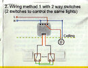
Alt-two-way-wiring.jpg
It was considered second switch would be a pull switch over the bed.

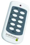
When I came to want bedside control however, it was easier to use a smart switch, and a remote control on bedside table Remote control.jpg and I still use this today, although can also use voice commands.

I swapped the switch in dinning room to a TP-Link smart switch so it could be used as a temporary bedroom, I used a smart button 1706179282062.png as the remote control, however wife preferred voice with the Nest Mini's we have, so the button reused as a door bell.
The problem as I see it is we expect to see a wall switch, and we know even in the dark where it is likely to be, if I knock off my remote from bedside table it is hard fumbling around on the floor to find it, the button is least is magnetic and will stick on any metal surface, and comes with a sticky backed metal disc so we can fix it.

I would prefer to have some thing that looks more like a switch so visitors recognise it. Blanking plates often are stainless steel so non magnetic, or have terminals to connect the earth, it would be nice to have a remote control which looks like a standard switch. But suppose people will get use to buttons and remote controls over time.

I do in fact have a pair of standard two way switches connected to a smart relay, Landing-light-relay-instructions3.jpg so have best of both, two way switches and voice control, plus of course can use the phone, but this is mainly just for visitors, we rarely use the switches, and one starts to wonder why we still need to wire in intermediate switches?

The problem is should one make become unavailable, or prove unreliable it is not easy to swap to another make, zigbee is not so bad, but I can't get all I want using zigbee. I have a house with in the main no neutral at switches, so best option for a smart switch is one with a battery, they last a few years on a battery and are easy to change without removing switch, but only found one make, and it is not zigbee.

I am sure there is a way with something like the google home app to integrate different makes, and make them work together, however getting a little old in the tooth now at 72 to work out how to set things up.

My son got me an Arduino Uno I got it to flash some LED, but never did get it to do useful work. Not a clue where it is now, my children seem to think I am a lot cleaver than I am, same with a drone, never did get the idea of flying it, ended up flying it into my self.

But if I can buy some thing ready made to do the job I want great. Simple things catch me out, I have an outside light which has a smart bulb in it stop working, I was trying all sorts, and wife said gardeners were using a grinder, have the switched it off, and yes simply switched off.

I it seems am getting like that one hit wonder 1706181788514.jpeg hee-hee, ha-ha.
 

DIYnot Local

Staff member

If you need to find a tradesperson to get your job done, please try our local search below, or if you are doing it yourself you can find suppliers local to you.

Select the supplier or trade you require, enter your location to begin your search.


Are you a trade or supplier? You can create your listing free at DIYnot Local

 
Sponsored Links
Back
Top