How do loads affect a PSCC reading?

Surely the PSCC test at source will be carried out when no loads are being used (or more correctly vice versa).
One would certainly expect so. However, this question posed in the OP was asking about what would happen if that were not the case. The Fluke manual says "Errors may occur due to preloading the circuit under test.". The unavoidable issue, as you go on to agree, is:
I don't know how other properties' loads can be avoided but, presumably they affect the situation most of the time.
If the measurements are being taken at appliances or accessories and the meter indicated a very low voltage would the tester not realise?
That obviously depends on the tester. However, I can see no mention in the Fluke manual that it will refuse to undertake a loop impedance measurement if the voltage is 'too low' - but maybe it does!
In any case, for the values at these points, Ze + R1+R2 is more accurate as a determination of the circuit but a measurement of the actual situation may be more indicative of what will really be the case in normal usage.
You're talking about EFLI (rather than L-N loop impedance) but, yes that's true - but really only because of the conventions as to which measurements one does, and does not, undertake with parallel paths disconnected.
I recall, I think, that you, John, have previously stated that the meter uses a standard nominal voltage, not the actual voltage, for this calculation in which case it would not matter what the actual voltage was. I am not sure that this is the case judging by the following from the Fluke manual - PFC. PSC Test
Accuracy Determined by accuracy of loop resistance and mains voltage measurements
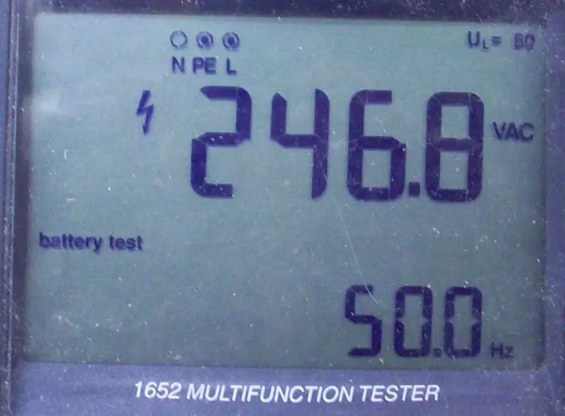
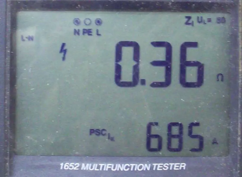
No, you recall back-to-front - and what you quote the manual as saying is correct. The illustration with my Fluke which I posted way back was:
Given that 0.36 x 685 = 246.6, it is clear that the meter is calculating PFC from the actual measured voltage, not a nominal one (230V or whatever).

Edit: Not a bad Ze for TT, eh? :) Before someone asks, given that my installation is TT, those measurements were obviously undertaken with 'parallel paths' still connected!

Kind Regards, John
 
Sponsored Links
Yes, sorry for back to front. I was confusing the two (Spark123's Megger and our Flukes).
Indeed. I can't actually make up my mind as to which is the more logical/reasonable. Given the context of this thread, maybe the Megger approach is more 'logical' - the Fluke PFC figure will depend upon what the installation's voltage 'happened to be' at the time of measurement - and that could theoretically be influenced (downwards) by large loads which happened to exist in nearby properties at the time.

Kind Regards, John
 
Sponsored Links
I have never striped down a meter but I would assume it works by measuring voltage then inserting a load and remeasuring voltage and from volt drop works out the loop impedance and prospective short circuit.

This would mean a load would not change the reading much but a switching of a load during the test would.

Do the test three times and we get different readings however that could be because the resistor in the meter is hot.

I would think where critical taking two readings is a good idea. In the main we know what to expect and if the result matches what we expect we say OK if not we retest.
 
I have never striped down a meter but I would assume it works by measuring voltage then inserting a load and remeasuring voltage and from volt drop works out the loop impedance and prospective short circuit.
Indeed, as I wrote, my Fluke 1652 appears to apply a load of about 19Ω for 10 milliseconds, and presumably measures the consequential VD in order to work out the loop impedance.
This would mean a load would not change the reading much but a switching of a load during the test would.
It wouldn't affect the loop impedance reading (unless, as you say, the load changed during the 10ms of the test) but, with a Fluke (but seemingly not a Megger), a load would change the calculated (hence displayed) PFC figure, since that is (with a Fluke) calculated using the actual voltage at the time.
Do the test three times and we get different readings however that could be because the resistor in the meter is hot.
The heating of the meter's resistor may be a factor. However, as above, in terms of the PFC (rather than loop impedance), the reading given by a Fluke can vary according to changing loads (within the installation or nearby premises), so it certainly makes sense to make multiple measurements - ideally spread over a significant period of time. With the apparent 'Megger approach', this is not a consideration, since the displayed PFCs are apparently not dependent on the actual voltage (although their resistors will still heat up!).

Kind Regards, John
 
Right, thanks, maybe it wasn't John who said it.

So the actual voltage doesn't matter with Meggers but not sure about Flukes.

I think it does it in voltage bands, so with a nominal 400v supply it uses 400v in the calc, 230v for 230v supplies and so on.
 
I think it does it in voltage bands, so with a nominal 400v supply it uses 400v in the calc, 230v for 230v supplies and so on.
Unless you have to tell it, it obviously won't know what the nominal voltage of the supply is. Are you perhaps saying that if it sees a voltage closer to 230V than 400V, it will use 230V for calcs, and vice versa?

Kind Regards, John
 
Yes, sort of explained on page 12 here: http://isswww.co.uk/manuals/MFT1500 user guide.pdf[/QUOTE]
Thanks. I think you're being rather modest (on the manual's behalf) by saying "sort of"! I reckon that:
Measured voltage > 45 V and < 80 V ... nominal voltage = 55 V
Measured voltage >80 V and <150 V ... nominal voltage = 110 V
Measured voltage >150 V and <300V... nominal voltage = 230 V
Measured voltage >300 V ................... nominal voltage = 400 V
...is more-or-less exactly what I was suggesting!

Kind Regards, John
 
Actually John you were suggesting a switchover voltage of 315V whereas it is actually 300V.
:D
 
Actually John you were suggesting a switchover voltage of 315V whereas it is actually 300V. :D
Hmm - I knew there was a reason why I had recently opened a bottle :)

I was, of course, talking about the general concept, rather than precise numbers! More seriously, I wonder why they did choose 300V rather than, as you suggest, going bang slap in between 230V and 400V with 315V? It's not as if the machine knows anything about 300V "being a nice round number"!

Cheers, John
 
Logarithmically, the mid point is 303V. Although the machine may not understand round numbers, its designer probably did!
 
Logarithmically, the mid point is 303V.
True, but I'm not sure that it would be particularly logical to have chosen the 'logarithmic mid-point' (i.e. geometric mean). In terms of the 110V/230V dividing line, the 150V they've chosen is not a rounded version of either the arithmetic (170V) or geometric (159V) mean - so what theories do you have about that one?!
Although the machine may not understand round numbers, its designer probably did!
Undoubtedly true. One is tempted to also wonder whether the designer was aso good at 'pulling reasonable-sounding numbers out of the air', without calculating any sort of mean.

Glass needs topping up!

Kind Regards, John
 
I'm still ahead of you on Riesling.

In practice it makes no real difference. My son would express 'pulling reasonable-sounding numbers out of the air', slightly differently.

I imagine it was an off-the-cuff design decision and in practice seems to work.

Nevertheless the logarithmic approach seems more logical to me in general. In the specific case the nominal voltages are not equally spaced but approximately double each time.

Happy drinking!
 

DIYnot Local

Staff member

If you need to find a tradesperson to get your job done, please try our local search below, or if you are doing it yourself you can find suppliers local to you.

Select the supplier or trade you require, enter your location to begin your search.


Are you a trade or supplier? You can create your listing free at DIYnot Local

 
Sponsored Links
Back
Top