Need a time delay circuit for my float switch and 12v pump?

The problem with float switches is you can design a circuit to do what ever, but the float switches can "bounce" on the liquid surface, so although in theory a circuit will work, in practice it doesnt because the float switches "bounce"
which is why quite often with bulk liquids a delay is used to allow for the movement of the liquid
 
Sponsored Links
Ban all sheds

It a manual for a Hydramaster spitfire 3.2
Truckmount carpet cleaning machine
 
The problem with float switches is you can design a circuit to do what ever, but the float switches can "bounce" on the liquid surface, so although in theory a circuit will work, in practice it doesnt because the float switches "bounce"

Which is why having 2 level switch settings operating a retaining contact is a better design - it takes the result of the bounce out of the equation. The switches don't need to be set that far apart, an inch or so may be adequate depending on how the liquid surface responds to the pump.
 
Being a mobile unit there will be surging of the liquid in the tanks as the unit accelerates, turns corners or slows down.

Hence the float switches will "bounce" when the liquid is close to operating them. This will increase contact wear.

Either

[1] you have to use float switches capable of taking the current and that includes the current under fault conditions until a safe shut down has occured.

[2] you have to remove the power circuits ( power to pump etc ) from the switches by using slave relays or contactors.
 
Sponsored Links
Ban all sheds

It a manual for a Hydramaster spitfire 3.2
Truckmount carpet cleaning machine
Is that what you've got?

If so why did it break, and why are you fiddling with it instead of fixing it properly?

If not, are you trying to copy the control system for a different application?
 
Being a mobile unit there will be surging of the liquid in the tanks as the unit accelerates, turns corners or slows down.
Yes, but he's hardly likely to be cleaning someone's carpets whilst he's driving the truck, is he...


Hence the float switches will "bounce" when the liquid is close to operating them. This will increase contact wear.
Not much, surely, if it isn't energised?

Either

[1] you have to use float switches capable of taking the current and that includes the current under fault conditions until a safe shut down has occured.

[2] you have to remove the power circuits ( power to pump etc ) from the switches by using slave relays or contactors.
If you're worried about contact wear then I don't see how either of those would reduce it.
 
The problem with float switches is you can design a circuit to do what ever, but the float switches can "bounce" on the liquid surface, so although in theory a circuit will work, in practice it doesnt because the float switches "bounce"

Which is why having 2 level switch settings operating a retaining contact is a better design - it takes the result of the bounce out of the equation. The switches don't need to be set that far apart, an inch or so may be adequate depending on how the liquid surface responds to the pump.
Once the lower switch has closed, the contactor will remain latched even if the switch bounces.

Once it gets to the top, as soon as the top switch has opened (even on a bounce) the contactor will open and will remain open even if the switch continues to bounce.
 
The problem with float switches is you can design a circuit to do what ever, but the float switches can "bounce" on the liquid surface
That isn't a problem with float switches, it's a problem with liquids.

so although in theory a circuit will work, in practice it doesnt because the float switches "bounce"
which is why quite often with bulk liquids a delay is used to allow for the movement of the liquid
This is just the usual breezer b*llocks. You're making it up as you go along.

The solution (no pun intended) is to use two switches, not a timer.
 
The problem with float switches is you can design a circuit to do what ever, but the float switches can "bounce" on the liquid surface
That isn't a problem with float switches, it's a problem with liquids.

so although in theory a circuit will work, in practice it doesnt because the float switches "bounce"
which is why quite often with bulk liquids a delay is used to allow for the movement of the liquid
This is just the usual breezer b*llocks. You're making it up as you go along.

The solution (no pun intended) is to use two switches, not a timer.

I'm afraid it is not b*llocks Softus. Many industrial control circuits that do not have analogue liquid level signals use delay timers on the digital level signals to allow for settlement. These are often programmed though in the controllers (PLCs)
 
I respect your views and knowledge, ricicle, however...

Need a time delay circuit for my float switch and 12v pump?
Many industrial control circuits that do not have analogue liquid level signals use delay timers on the digital level signals to allow for settlement.
I respect your views and knowledge, ricicle, however...

Need a time delay circuit for my float switch and 12v pump?
This is not an industrial control situation, so my comment was made in the context of the topic, and was an observation on breezer's apparent compulsion to post something on every topic, even when he doesn't have the first clue what's going on.
 
If you're worried about contact wear then I don't see how either of those would reduce it.

Mechanical wear is not reduced but contact wear is significantly reduced.

One switch closes to energise the contactor and is then shorted by the latching contact on the contactor. No matter how often the switch opens and closes ( bounces ) once the contactor is closed the switch is not switching current.

The other switch opens to unlatch the contactor. Assuming the first switch is now open ( as it should be in the level control design is correct ) then as soon as the contactor opens the voltage across this switch is removed. No matter how often the switch opens and closes ( bounces ) once the contactor is open the switch has no voltage applied.

If the contactor has a separate contact for the power to the controlled pump then the switches only have to carry the very small current for the contactor coil and only the break switch has to cope with the back EMF voltage when the contactor coil is de-energised. Suitable arc suppression can be added to the switch.
 
They are conductivity probe units, the ones we use need a series of conductivity probes set at different heights to set the on/off switching of the system.
Little bit different to using a float switch.
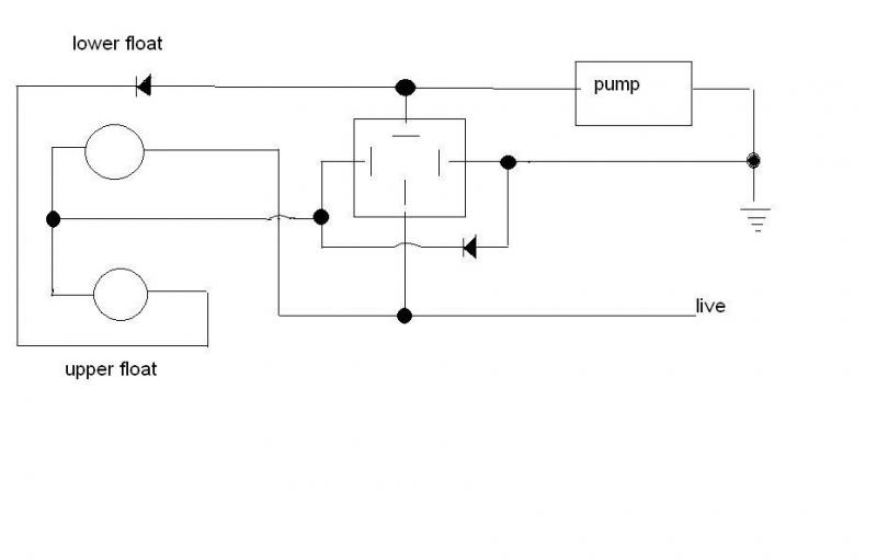
Still think using 2 float switches, a relay and a couple of diodes is relatively easier!
 
The only reason for the switch welding would be too much current flowing through it owing to ommitting the diode or a spike caused by the voltage caused by the relay switching off.
This can be overcome by fitting a reverse biased diode across the relay coil:
So all you need are 2 switches, a couple of 1N4001 diodes and a 12v relay!
Having 2 relays should have worked too, ignoring the spike mentioned above the the 2 relay coils would have been wired in parallel, one relay used for control and the other to switch the pump.

spark123
I've re drawn your schematic Im worried about the load from the pump on to port 87 and there being a positive from live on to port 30 and then onto the float switches
Surly one of them is going to be overloaded
Just wondered why you drew your diagram so the switches wear the other way round

wear are you from


I have been down to the machine today and re-wired it up as above
I had thoughts in the back of my mind about the above and it came true!!!
The lower float switch has some how split (the one I substitute from the low water engine stop) showing a no circuit all the time no matter what direction the magnet is in
I have tried taping it just like before but it still insists to show no circuit what ever
And now it is completely knacked
So what next bright sparks?
 

DIYnot Local

Staff member

If you need to find a tradesperson to get your job done, please try our local search below, or if you are doing it yourself you can find suppliers local to you.

Select the supplier or trade you require, enter your location to begin your search.


Are you a trade or supplier? You can create your listing free at DIYnot Local

 
Sponsored Links
Back
Top