Please help. Light curcuit issue (Diagram attached)

What does the other switch on the 2 gang switch do? Nothing?
Not a thing...it was taped up when i moved in.
Com port has live to the kitchen lights and the bridge is for another live to living room switch.

The 2 wires i put in L1 ports are what I assume go to both kitchen lights too. As i take one out and one light stops working.
 
Last edited:
Sponsored Links
Not a thing...it was taped up when i moved in.
Com port has live to the kitchen lights and the bridge is for another live to living room switch.

L1 and L2 ports are what I assume go to both kitchen lights too. As i take one out and one light stops working
Sorry, you've lost me.
 
Sorry, you've lost me.
Sorry im multi tasking.
In short. Only 1 switch powers both lights in the kitchen now. The seing switch on the 2 gang does nothing.
The kitchen switch has 1 live wire from the kitchen lights in the common terminal. Another wire in the second common (bridged) passes power to the living room switch. And then the two L1 terminals are somehow attached to the kitchen lights too. But only one switch does anything.
I assume its a 2 gang so the living room has power? The second switch does nothing.
 
Then why not just have a 1 gang switch, with the kitchen light wire in L1, and all the feeds in the common?

There were four wires
One to the both kitchen lights?
One main feed.
One feeding the switch controlling the living room.
What does the remaining wire do?

I would have expected the main feed wire to go in one common, with a link to the second common, and the wire feeding the lounge light also in that second common. And the kitchen lights wire in one of the L1s.

But that leaves one unknown wire left.

I wonder what, if anything, that wire does?
 
Sponsored Links
Then why not just have a 1 gang switch, with the kitchen light wire in L1, and all the feeds in the common?

There were four wires
One to the both kitchen lights?
One main feed.
One feeding the switch controlling the living room.
What does the remaining wire do?

I would have expected the main feed wire to go in one common, with a link to the second common, and the wire feeding the lounge light also in that second common. And the kitchen lights wire in one of the L1s.

But that leaves one unknown wire left.

I wonder what, if anything, that wire does?
I started a new thread for this but perhaps wasn't needed.

I was debating swapping for a single. but the fact I have 2 separate wires in the L1 terminals made me think I can get them working independently. Somehow.

This is where I'm at currently. If this helps?... (I can probably get someone to remove the other thread?)

Untitled.png
 
You seem sure, according to your diagram, that one of the reds at the switch connects to some black wires at the kitchen lights.

Are you SURE about that?

How have you tested for that, and were all the light bulbs removed when you did that?
 
You seem sure, according to your diagram, that one of the reds at the switch connects to some black wires at the kitchen lights.

Are you SURE about that?

How have you tested for that, and were all the light bulbs removed when you did that?

I used a multimeter and tested every wire wirh every other wire with lights removed. All loose wires. tested from all sockets and lights. A black from each of the kitchen lights ran to 1 red in the socket. I got a reading from each of them when connected on the multimeter so assumed they ran a live feed to the switch?
When lights connected that same red in switch has voltage.
Whats odd though is that when testing the two blacks at each light together I get no reading in multimeter. Only when i go each light to that red in switch do it say they have a connection.
 
I reckon there might be something like this with the live supply in there
1721335739408.png

and the 2 reds are something like:
1721336003759.png

but how that figures with your sketches I don't know, by the way well done on the way you have tried to portray the situation.
I feel you have some errors in there somewhere but without additional testing we will not get to the bottom of this.

As you have already concluded putting one red wire into each 'L1' appears to operate the lights independantly of each other and from this distance I don't see why you should not do that if you wish.
 
Last edited:
I feel you have some errors in there somewhere but without additional testing we will not get to the bottom of this.
I think you are right. Thats all I can test with multimeter and visual as is. I am going to pull all the flooroards up tomorrow night and get to the bottom of this. there might be a junction of some sort?
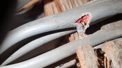
I did just have a peek and saw this... I assume its the oven. But now i need to see every last bit.

IMG-20240712-WA0011.jpeg20240712_212240.jpg

As you have already concluded putting one red wire into each 'L1' appears to operate the lights independantly of each other and from this distance I don't see why you should not do that if you wish.
They work independently of each other only when one of the L1 wires is removed. Soon as i put both into each L1 terminal both lights work together only.
 

DIYnot Local

Staff member

If you need to find a tradesperson to get your job done, please try our local search below, or if you are doing it yourself you can find suppliers local to you.

Select the supplier or trade you require, enter your location to begin your search.


Are you a trade or supplier? You can create your listing free at DIYnot Local

 
Sponsored Links
Back
Top