Cavitation on Rayburn Central Heating

I don't understand your system.
The HW cylinder feed connection is not shown - is it before or after the pump?
The hot flow pipe goes from the stove up into the cistern via the check valve.
So you get thermosiphon up the red pipe and down the blue from the header tank? I can't see any benefit of that, and warming the header tank is undesirable as it can lead to algae growth.
The swing check valve can always open and let water into the cistern if the water expands too much.
The swing check valve needs to open for the thermosiphon to happen.
The system can thermosiphon with the cistern initially
So why do you want the thermosiphon through the boiler only? Maybe the current arrangement doesn't vent air adequately, causing the pump noise.
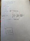
Changing the red pipe to the tank to an up-and-over vent (no connection below the water level) would prevent the unwanted flow loop from the tank, and give better venting.
The swing check valve can always open and let water into the cistern if the water expands too much.
There's no need, expansion can via the blue pipe.
 
Sponsored Links
Agree that that the check valve should be removed and the vent re instated up and over.
 
I get cavitation with cold water (fire turned off) as well as hot.
I think your problem is the head at pump suction is too low. I have some Grundfos data, which says for UPS 15-50 minimum dynamic head 1.3m, for UPS3, minimum 0.5m. These are at 75°C, doesn't give figures for lower temperature. If you have 0.5m static, the head at pump suction is much lower due to headloss from the tee on the blue pipe, the boiler, and the red pipe to the pump suction.
I looked at the Wilo site but couldn't find anything on suction pressure, do you have any data?

My suggestion is - change the cold feed to the pump suction, up-and-under to avoid convection warming the tank. Also mod the vent pipe as above. That gives the preferred arrangement, boiler - open vent - cold feed - pump. That should cure it, if it doesn't you might need to lower the pump as well.
Presumably the designer is taking some responsibility for the problem?
 
The HW cylinder is fed from the manifold, as are the radiators.

The data I found on Wilo NPSH is here, page 7:

https://cms.media.wilo.com/cdndoc/wilo252578/3625152/wilo252578.pdf

If the check valve is removed and the vent installed up and over, will the issues with low pressure at the pump inlet still remain as the inlet pressure to the pump comes from the static head in the cistern, acting down the cold return pipe, through the boiler and back to the pump inlet?

I'm not clear on the suggestion to "change the cold feed to the pump suction". I presume you mean hot feed vent up and over the cistern, then cold feed down to pressure side of the pump (not the feed side). Is that correct? Do you think you could do a basic skecth?

Many thanks
 
Sponsored Links
I'm not clear on the suggestion to "change the cold feed to the pump suction". I presume you mean hot feed vent up and over the cistern, then cold feed down to pressure side of the pump (not the feed side). Is that correct? Do you think you could do a basic skecth?

Many thanks
The suggestion is to tee in the cold feed into the pump (red pipe) inlet, then remove the next (blue) section of piping and cap it just above where all the returns come back, you will then have the traditional (from the boiler) Vent, Cold feed, Pump, VCP system, the distance between the vent and cold feed should be less than 150mm, the up-and-under (or under and up) refers to where you tee in the cold feed, just bring it down a few inches under the pump inlet and then loop it back up into the inlet, system 3 gives a idea of the VCP system.
Also, a screen shot of a VCP system but the cold feed was not carried up and under.
1720932111367.jpeg

1720932691078.png
 
Last edited:
I'm a bit tied up at the minute, but I'll do one later (in case johntheo's post isn't enough)
Sketch attached. I thought I'd got the orientation right but apparently not!
Hope it's legible. The top of the loop over the header tank should be 450 mm minimum above the top water level.
A minor point, and maybe the drawing is diagrammatic only, but I prefer to take the vent connection from a horizontal run, rather than across the top of a tee, as that gives the water a head start towards the vent.

From the Wilo data the setup looks borderline, as you only have 0.5 m head at the pump. I don't suppose you'll run at 95°C but if you're at say 75° it needs about 3 m head in theory. Probably worth trying it and see how it goes, but you might need to lower the pump.

Come back with any queries!
 

Attachments

  • Heating layout.pdf
    1.6 MB · Views: 26
See attached schematic I drew up from the various comments. Is this more or less what is being suggested?

One question, can this circuit thermosiphon? I currently have the thermostat up near the header tank and pump in the loft, and the water rises up when the fire starts which activates the thermostat and starts the pump. I presume in the proposed circuit the water will not thermosiphon and so the pump thermostat needs to be down directly next to the rayburn?
 

Attachments

  • IMG_3444.jpg
    IMG_3444.jpg
    190.9 KB · Views: 47
See attached schematic I drew up from the various comments. Is this more or less what is being suggested?

One question, can this circuit thermosiphon? I currently have the thermostat up near the header tank and pump in the loft, and the water rises up when the fire starts which activates the thermostat and starts the pump. I presume in the proposed circuit the water will not thermosiphon and so the pump thermostat needs to be down directly next to the rayburn?

Schematic is correct.

You should still get thermosiphoning even though the primary flow and return are normally 28mm in a solid fuel system, also the pump is on the same circuit which will also restrict the thermosiphon, the HW cylinder is normally used as a heat sink in the event of a power outage/pump failure and the system is normally plumbed somewhat like my schematic, if the stat is fixed in place then you can get a pipe stat which straps onto the pipe and locate it much closer to the boiler, also suggest, if not allready done so, to use pipe insulation especially on the boiler flow pipe to help the thermosiphon effect.

Should also have said that horizontal pipe runs have a big effect on thermosiphon circulation, the cylinder is located as directly above the boiler as possible.
 
Last edited:
hi John

Will the thermosiphon still work given the return loop is through the pump?

Also, if I plumb the tank so it thermosiphons and is a heat sink, then presumably it will not thermosiphon when the pump turns on and directs water through the radiators. It looks like people solve this issue by using an injector tee or are there other ways around this?

Nathan
 
Last edited:
It will have some restrictive effect but not huge, I have seen a number of systems with the pump either on the flow or return with no big problems, the horizontal pipe runs (see above) will have a far greater effect but by installing the (a) stat close to the boiler and setting its SP suitably after firing the system then should work but your system certainly does not seem to have been designed by a solid fuel genius, to say the least.
 
Thanks John,

Do you have any feedback regarding the injector tee and whether there is an alternative to that?

Nathan
 
Just looked through this thread whoever designed that pipework layout for a solid fuel cooker hasn't a clue!
You need to check out prefered layout in instalation manual it's avaliable on Harworth Heating website if you don't have a copy.
We were for many years agents for Stanley cookers so this sort of installation was every day stuff.
 

DIYnot Local

Staff member

If you need to find a tradesperson to get your job done, please try our local search below, or if you are doing it yourself you can find suppliers local to you.

Select the supplier or trade you require, enter your location to begin your search.


Are you a trade or supplier? You can create your listing free at DIYnot Local

 
Sponsored Links
Back
Top