This is one of the best installation schematics I've come across.
What would be typical settings for the high and low stats??
What would be typical settings for the high and low stats??

I mentioned the designer's input in an ealier post!Just looked through this thread whoever designed that pipework layout for a solid fuel cooker hasn't a clue!
I'm still not clear how it's meant to work. Is your system currently piped like your #24, or is that a option to rectify things?hi John
Will the thermosiphon still work given the return loop is through the pump?
Also, if I plumb the tank so it thermosiphons and is a heat sink, then presumably it will not thermosiphon when the pump turns on and directs water through the radiators. It looks like people solve this issue by using an injector tee or are there other ways around this?
Nathan
We were doing min/max control stats long before Rayburn caught on lolThis is one of the best installation schematics I've come across.
What would be typical settings for the high and low stats??
It becomes pretty obvious why proper installation is important because of the tiny circulating force generated with gravity circulation, for example if you use those flow/return temperatures of 75C/40C then a circulating height of say 2.5M will produce a circulating force/head of only 0.053M or 2.1 inches compared with a pumped; pump head of say 3.0M, my HW cylinder coil circulates10LPM through the coil at a 3M pump head so the circ flow will only be ~ 1.33LPM at the gravity generated head of 0.053M, if the coil flow/return is/was 75C/40C at this flowrate then its output is 3.25kw.We were doing min/max control stats long before Rayburn caught on lol
I worked with a brilliant guy called Mike Barnat-Mills he did internal design for twin burner Stanley's designed the Whatson and Sandyford cookers
He realised 50 odd years ago that back end protection was required as well as high limit.
We used 2 pipe stats one on return set at 40C that pump was wired through so when fire dropped pump stopped.
Another on flow feed by permanent live set at 75C to prevent boiling.
Yes, theoretically, because this minimum required 0.5M head at 75C IS (IMO) the NPSHr, so even if the flow temperature is higher resulting in a much higher vapour pressure then there is still plenty of NPSHa (NPSH available) to deal with this, the 6.65M above is, again IMO, the (available) NPSHa.I've looked at inlet pressure requirement for a number of pump suppliers. It seems to vary a fair bit, and somewhat inconsistent, but I think there's a good chance 0.5 m head at 75°C will be OK. That's for the Grundfos UPS 2, and I don't see why different pumps should vary much. Water vapour pressure at 75°C is 3.85m, so with atmosphere 10m and 0.5m static close to the pump suction (as it is on our suggested layout), pump NPSHr = 10+0.5-3.85 = 6.65 m, which I'd expect to be OK. A typical industrial centrifugal pump has an NPSHr ~ 3m. Worth a try anyway.
Just to be clear - the NPSHr is the head in m (absolute) required by the pump. It varies with the pump flow on the Q/H curve, but not with temperature. The NPSHa varies with temperature via the vapour pressure (as you know). CH pump suppliers don't give an NPSHr curve (at least I've not seen one), they give the required pressure at the pump suction, at a number of temperatures, which isn't the same. It might be better if they gave the NPSHr and left it to the installer to ensure the NPSHa is greater (with a safety margin) using the temperature, heads and pipe losses. That's what happens on industrial applications.Yes, theoretically, because this minimum required 0.5M head at 75C IS (IMO) the NPSHr, so even if the flow temperature is higher resulting in a much higher vapour pressure then there is still plenty of NPSHa (NPSH available) to deal with this, the 6.65M above is, again IMO, the (available) NPSHa.
Just to be clear - the NPSHr is the head in m (absolute) required by the pump. It varies with the pump flow on the Q/H curve, but not with temperature. The NPSHa varies with temperature via the vapour pressure (as you know). CH pump suppliers don't give an NPSHr curve (at least I've not seen one), they give the required pressure at the pump suction, at a number of temperatures, which isn't the same. It might better if they gave the NPSHr and left it to the installer to ensure the NPSHa is greater (with a safety margin) using the temperature, heads and pipe losses. That's what happens on industrial applications.
That's right. The required heads quoted by suppliers at different temperatures don't always correspond too well with the change in vapour pressure, as on the UPS2. That's what I meant by somewhat inconsistent, the Wilo data is a bit odd, I think they may mean 75°C when it says 50°.Edit: I was still thinking of the inlet pressures in NPSH terms (incorrectly I now think) so NPSHr is 10+0.5-3.86, 6.64M, (at 75C) and 10.0+2.8-7.0, 5.8M, (at 90C), so looks right?.

What sized flow/return pipes to the cylinder as currently supplied from the manifold?Thanks for all the help everyone.
In my post #24, the schematic is the planned schematic to rectify the current issues. It creates a fully pumped circuit, where a manifold distributes water to the DHW tank and two radiators. The pump switches on via a thermostat positioned close to the boiler. If the water from the Rayburn drops below a set point, say 65 degrees, the pump stops.
As above, the cylinder should be stand alone.In post #31 by Jon, the schematic shows a primary gravity thermosiphon circuit between the wood stove and the DHW tank. A pump on the return line with an injector tee is shown for the radiator circuit.
I like the gravity fed thermosiphon circuit as the tank acts as a good buffer for when you need to ramp up the fire to cook bread for example. However. it is a bit problematic for me to plumb like that now (not impossible just a bit difficult).
Do people think the schematic I drew in #24 is significantly inferior to the thermosiphon option?
In the injector tee circuit, the cold water feed looks to act primarily on the supply side of the pump.
I suppose I am asking, in a wood stove arrangement, whether pumping with a manifold is ok, desirable or inferior to the thermosiphon/injector tee setup?
That's why the pump is cavitating?.Couple more questions:
1) The static head on the pump inlet for the injector tee setup seems to act down the feed pipe, through the injector tee, through the stove, through all the radiators and back to the pump. That seems like a lot of static head reduction.
It posssibly should, @Exedon will know.2) I presume given the (1), the injector tee and pump in loft would not work?
Nathan
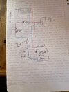
That looks reasonably OK IMO.Here is an example of the injector tee and pump in the loft and vent and feed going to the pump inlet.
The tank thermosiphons and the radiator circuit is pumped.
I should be able to get 1m static head between top of water in header tank and pump in this arrangement.
Comments?
No, the static head on the pump inlet is just the height between the pump inlet and the F/E tank water level, which we understand is 0.5 m.1) The static head on the pump inlet for the injector tee setup seems to act down the feed pipe, through the injector tee, through the stove, through all the radiators and back to the pump. That seems like a lot of static head reduction.
Don't understand. Is the F/E tank also in the loft (above the pump)? I don't know anythng about injector tees.2) I presume given the (1), the injector tee and pump in loft would not work?
That was on the original layout, with cold feed to the boiler return. We hope to have cured it with the revised layout.That's why the pump is cavitating?.
If you need to find a tradesperson to get your job done, please try our local search below, or if you are doing it yourself you can find suppliers local to you.
Select the supplier or trade you require, enter your location to begin your search.
Are you a trade or supplier? You can create your listing free at DIYnot Local