Cavitation on Rayburn Central Heating

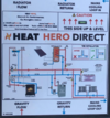
The Heat Hero Direct seems like an interesting product and related to this discussion:


It also comes in a "gravity" model:


The gravity model seems to have several injector tees. I'm not sure if the "direct" has injector tees too or whether it simply has through ports and its main feature being a built in cooling loop, in the event of water getting close to boiling.

There is a good video on the heat hero gravity in this link:

 
Sponsored Links
I'm getting confused here!
You've posted several alternative layouts. Is it your intention to modify your original layout as has been suggested (fairly straightforward), or to change to something else?

We've asked several times about the designer. Is he still on the case, and will take responsibility for any problems, eg by not having a heat dump rad?
 
To be honest I'm a bit concerned with having a close coupled feed which means the cold feed is not directly supplying the return pipe of the stove. In the event of the stove boiling, it seems the cold feed would not easily supply the wet jacket of the stove and it could potentially be damaged. that's why I was exploring other options before going down the close coupled feed option.
 
Sponsored Links
The thermostat sensor T is mounted right on top of the boiler so there was probably little or no gravity circulation before the circ pump cut in?, just wondering why its mounted there and why the designer didn't, at least originally, install the vent properly, up and over the F&E cistern, what is the horizontal distance from the vertical flow/return pipes to the manifold?
 
Unfortunately the designer has decided not to answer any questions after selling their equipment and design and then learning it did not work....

The issue with gravity circulation is that the radiators are located on the ground floor and the manifold in the loft. There are a number of sections of horizontal runs. Likewise with the DHW tank, it has a couple of meters of horizontal pipe that connect it back to the manifold.

What I think I will try is shown in the attached drawing. It is modelled on the Heat Hero Direct circuit. I spoke to the man from Ireland who sells them. One thing I have learnt from studying this is that it shows the correct configuration of tee joints to avoid water going the wrong way. The tees in the original design I had are certainly incorrect and lead to the water being directed up towards the header tank. With the latest design, the cold feed is dipped as per the Rayburn design, and the cold water enters the Tee from below. Thus, the pumped flow does not hit the wall of the T (like the original) and the heat should not flow up to the header tank.

The cold feed is also connected directly to the stove, so in the event of boiling, cold water is supplied directly to the wet back to cool it off.

According to what I have watched on the Heat Hero, the pump will draw down the water in the expansion pipe when it runs but not so much that it will draw in air (provided the header tank is at least 1m above the pump).

The innovation the heat hero has is that it also has a built in cooling loop, in case of boiling. However, with the cold feed entering the stove directly, any boiling should be immediately replaced by cold water from the header tank and thus I don't think I need this feature.

So that is what I think I will try.
 

Attachments

  • Final schematic.jpg
    Final schematic.jpg
    326.4 KB · Views: 27
  • heat hero direct.png
    heat hero direct.png
    623.9 KB · Views: 22
Unfortunately the designer has decided not to answer any questions after selling their equipment and design and then learning it did not work....
OK, at least we know now. Sounds like a right cowboy. I wonder where that leaves him legally, in Australia.
 
If you draw a line midway between the flow and return on the cyliner coil and the same, midway between the flow and return on the boiler, how much higher (if any) is the cyliner "line" above the boiler "line".?
 
Hi John,

The stove and radiators are on the ground floor and the cylinder, pump and manifold are in the loft section of the top floor. See attached drawing. Coil to Coil vertical height is just under 3m.

However, note the cylinder is not an open vented type. It has a pressure release valve.

Nathan
 

Attachments

  • Stove to tank.png
    Stove to tank.png
    482.2 KB · Views: 20
Hi John,

The stove and radiators are on the ground floor and the cylinder, pump and manifold are in the loft section of the top floor. See attached drawing. Coil to Coil vertical height is just under 3m.

However, note the cylinder is not an open vented type. It has a pressure release valve.

Thanks Nathan,
The flow/return pipes from the boiler to the manifold will be obviously rising, what about the pipes from the manifold to the cylinder coil? are these even slightly rising? and what is the horizontal distance between them and the cylinder? , a simple sketch would help.
You can see below, the tiny circulationg heads involved with gravity flow, at flow/return temperatures of 55C/25C the circulating head is only 0.034M and still only 0.053M with flow/return temps of 75C/40C, compared tpo a pumped circulating head of anything from 2.5M to 6.0M.

1721721110661.png
 

DIYnot Local

Staff member

If you need to find a tradesperson to get your job done, please try our local search below, or if you are doing it yourself you can find suppliers local to you.

Select the supplier or trade you require, enter your location to begin your search.


Are you a trade or supplier? You can create your listing free at DIYnot Local

 
Sponsored Links
Back
Top