In terms of hardware you are going to need:
Panel Digi Modem port extension lead - this is the grey lead that should come with panel if required or you can bodge with the Dupont leads.
Comport adapter JAL-0001 - sometimes come with a SmartCom or try eBay, again you could bodge this with Dupont leads at your own risk.
Raspberry Pi Zero 2W (with header unless you can solder your own) - I had already but you could use any Pi 0/3/4/5 you have laying around.
It would be a good idea to have a genuine PSU for the Pi available as well whilst setting it up...
Suitable Case with header exposed - I had already but this is the same:
Clear Plate Acrylic Case for Raspberry Pi Zero 2 W Case with Aluminum Heatsink<br>Features: 100% brand new and high quality<br>Simple and transparent, easy to install.<br>Acrylic material case.<br>With the hole for heat sink design.<br>Tranparent color .<br>Use for Raspberry Pi Zero 2...
www.ebay.co.uk
Good Quality MicroSD Card (8GB/16GB is fine) - I had already but these are good for the price:
USB MicroSD Card Reader (or a way to write an image to the SD card) - I had already
Level Shifter:
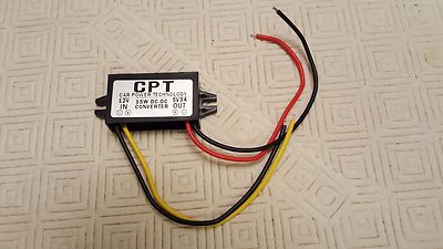
DC<>DC Convertor:
Max power consumption: 15W. Output current: 3A (MAX). Converter Size: 6.50 2.70 1.40cm.
www.ebay.co.uk
Selection of Dupont cables:
Selection of tools including soldering iron, solder, wire strippers etc.
Selection of cable ties, heatshrink and ferrules etc.
I think that is it!
I will write the connection guide up in the next few days and then how to configure the software afterwards...