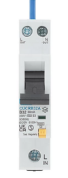
Bi and Omni directional RCD's how can one tell what has been fitted.

I can't be bothered to read the whole thread again so it might have already been said.


However, over-thinking has been prevalent and along with the poor choice of words; namely bidirectional and unidirectional; it has led to confusion.

As far as I can tell the terms just mean that unidirectional devices will be damaged should the power flow in the reverse direction - as might happen with PV or generators etc. - and bidirectional ones will not.

It is nothing to do with being able to magically somehow work with the power in the opposite direction.
 
Sponsored Links
However, over-thinking has been prevalent and along with the poor choice of words; namely bidirectional and unidirectional; it has led to confusion.
There is certainly confusion, and I agree that the choice of those words helps to exacerbate that confusion.
As far as I can tell the terms just mean that unidirectional devices will be damaged should the power flow in the reverse direction - as might happen with PV or generators etc. - and bidirectional ones will not. .... It is nothing to do with being able to magically somehow work with the power in the opposite direction.
Yes, I think that's where the discussion has got to. I still can't see how any RCD could fail to detect (and act upon a residual currenmt in either direction - so, as you say, one can but presume that the perceived problem is that some may be 'damaged' if the supply is connected to the unintended side (since the innards of the device will then remain powered after the device has operated).

However, as I've said, I still have not find a way to understand how the device could be damaged by the innards continuing to be powered after it has operated, since I see no difference between that situation and the one in which the innards remained continuously powered for months or years whilst in service.

I would add that I find this concept of "power flow" to be rather strange and confusing, since the only thing which can actually 'flow' is current. I would think that what we should be talking/thinking about is simply 'which side of gthe device is connected to the supply'.

Kind Regards, John
 
... I never make any claims of infallibility or omniscience, and quite often 'miss' things or get things wrong .....
... and no sooner written than proven :) Whilst pondering in bed last night, I cam,e to realise that I had been wrong, at least in a literal sense, when I wrote...
I'm afraid I can't, ("work it out myself") and it still seems to me that it would be impossible - so, if I'm wrong, I need help to understand, not 'criticism'.
...... Consider the simplest case of a battery connected to a light bulb with a bit of 2-core cable. You have access to part of that cable (the separate cores if you wish) but cannot see which end of the accessible bit of cable is connected to the battery and which is connected to the lamp. How on earth (without cutting the cable, hence interrupting the circuit) could you ascertain which end of the bit of the cable was connected to the battery and which to the bulb? .... The same would seemingly be true if it were an AC supply and any sort of load.
I now have twigged that if one has access to two points a significant distance apart on one conductor and one point on the other conductor, then one can determine which end of a cable is connected to the supply (and which is connected to the load), because of the small voltage drop across the length of conductor between the two test points on one of the conductors.

So, yes, it would be possible to design a device that would only operate in response to residual currents when the supply was connected to a particular set of its contacts - one could start with a 'normal RCD' and add circuitry as implied above to detect which side was connected to the supply, and then somehow use that to disable RCD operation (in the event of a residual current) if it had been ascertained that power was connected to the 'wrong' set of terminals.

However, although I now realise that such would be theoretically possible, it would seem to be a pretty crazy thing for anyone to design - what possible advantage would/could there being in disabling residual current detection functionality when the supply was connected to the 'wrong' terminals? [a bit like designing a car with a braking system, half of which was disabled if one did not fasten one's seat belt ! ]

However, per recent posts (from me and others), I think this is probably moot. Even if (as above) one could theoretically design one, I don't think that (m)any of us now believe that any of the RCDs/RCBOs out there will fail to detect residual currents "because they have wired the wrong way around", the reason it is said that some 'must be installed the right way around' presumably being related to perceived 'risks' (which I don't yet understand) to the device, rather than to residual current detection functionality.

Does anyone agree with that? :)
 
However, as I've said, I still have not find a way to understand how the device could be damaged by the innards continuing to be powered after it has operated, since I see no difference between that situation and the one in which the innards remained continuously powered for months or years whilst in service.
The difference is what is powered when the device trips.
When the RCD detection circuit trips - as opposed to the thermo-magnetic-mechanical arrangement for the MCB part - it will power a solenoid to trip the contacts. The solenoid and associated supply/control only needs to be rated for intermittent operation - and to get a good powerful operation it may well be designed for high current but only for a short time.
So what's the easiest way to cut power to the solenoid after the device trips ? Power it from the output - then when the contacts open, solenoid power goes off.
If you swap supply & load then the trip solenoid remains powered even after the contacts have opened.
 
Sponsored Links
The difference is what is powered when the device trips. ... When the RCD detection circuit trips - as opposed to the thermo-magnetic-mechanical arrangement for the MCB part - it will power a solenoid to trip the contacts.
It will [your "as opposed to..." bit obviously only being relevant if the device is an RCBO]
The solenoid and associated supply/control only needs to be rated for intermittent operation - and to get a good powerful operation it may well be designed for high current but only for a short time.
Indeed so.
So what's the easiest way to cut power to the solenoid after the device trips ? Power it from the output ....
That would obviously achieve what you say, but I don't really see why it should be necessary - since, once the device trips, there will no longer be a 'residual current' (L-N imbalance), so the circuitry which had been causing the solenoid to be energised should surely stop 'causing it to be energised', shouldn't it? Furthermore, I presume that the solenoid merely 'trips' ('triggers') a mechanical mechanism in order to open the device's contacts, so there is no need for it to remain energised.
- then when the contacts open, solenoid power goes off.
As above, wouldn't you expect (as I would) "the solenoid power to go off" as soon as there was no residual current flowing through the device (because it had tripped)?
If you swap supply & load then the trip solenoid remains powered even after the contacts have opened.
As above, if that were the case (which I doubt), why on earth would anyone design it like that - since, on the face of it, the only thing it would achieve would be to put the device 'at risk' if it were connected one way around?!
 
That would obviously achieve what you say, but I don't really see why it should be necessary - since, once the device trips, there will no longer be a 'residual current' (L-N imbalance), so the circuitry which had been causing the solenoid to be energised should surely stop 'causing it to be energised', shouldn't it?
I'll admit, I hadn't thought of that.
 
I'll admit, I hadn't thought of that.
Fair enough - and I'm very guilty of quite often ;overlooking' or 'missing' things, even 'pretty obvious things sometimes :)

Do I take it that, now you have been prompted to 'think of that', you would now agree that it somewhat undermines your suggested 'explanation' ?
 
I must admit that it would be very rewarding to get a credible explanation and then see what we are missing. I`m starting to get that Monty Hall feeling feeling about this one. I`d be more than happy to get the answer then kick myself for missing it.

I think I`ll look on Amazon to see if they are selling those "learning curves" again. ;)
 
I must admit that it would be very rewarding to get a credible explanation and then see what we are missing.
Very much so. We've seen a few near-assertions from people who seem to think that they know the 'obvious explanation' but they either haven't shared enough detail or else have provided 'explanations' which make no sense to me (maybe because of my 'stupidity')..
I`m starting to get that Monty Hall feeling feeling about this one. I`d be more than happy to get the answer then kick myself for missing it.
Again, quite so. Despite the fact that some people have suggested or implied that I have been "arguing for arguing's sake" (or trying to 'increase my post count' !!) I genuinely don't fully understand what this is all about. I therefore presume that I must be 'missing something', maybe something 'obvious' - and, like you, would be only too pleased if someone could help me understand what I'm missing and/or 'why I am being stupid.

As things stand, it still seems to be the case that no-one has really offered any suggestions as to how a (credible) RCD could fail to detect a residual current if it were connected 'the wrong way around' (or why anyone would produce a device with such functionality) - and the nearest we seem to have got to any 'explanation' having been suggestions (not all particularly credible, in terms of detail) that the device may be damaged if installed in a manner contrary to its marking and the MIs.

However, there are surely plenty of things that might be damaged if someone connects wiring to its terminals in a fashion contrary to that indicated by markings and/or MIs, so, if that were the only issue with the RCDs, then why single out this one situation for an 'Emergency Amendment' to BS7671.

However, it seems worse than that. If there are some RCDs which could be damaged by being connected contrary to their markings, then, again, that would be true regardless of whether "bidirectional power flow was possible" (which is the only situation to which the proposed 530.3.201 applies.

Also, no-one yet seems to have commented upon my having reminded us that no RCD could possibly ever protect against an L-E fault which was on the side of the device which, at the particular moment in time, happened to be 'the supply side' - which seems to introduce some doubt/uncertainty into the whole issue we are discussing.

It does seem that those of us who are prepared to admit that this is the case must surely be 'missing something'??

Kind Regards, John
 
[a bit like designing a car with a braking system, half of which was disabled if one did not fasten one's seat belt ! ]
They did design caravans where the over run brakes only worked in one direction, which did result in some runaways when unhitched on a hill.

However back to start, one is doing an EICR and one sees a MCB, RCD, RCBO, Isolator which has load marked on one side, if the load is marked on a side which could still be powered when the device is switched off, what is the code?

Be it a RCD/RCBO which is type AC or one where load in marked, what should the codes be. It seems the old idea of "Installations designed after" and "Existing installations that have been installed in accordance with earlier editions of the Regulations may not comply with this edition in every respect. This does not necessarily mean that they are unsafe for continued use or require upgrading." is no longer true.

I have not got a copy of the 18th maybe some can confirm or say if that clause is still in the book.
 
However back to start, one is doing an EICR and one sees a MCB, RCD, RCBO, Isolator which has load marked on one side, if the load is marked on a side which could still be powered when the device is switched off, what is the code ?
As below, that's presumably down to the judgement/discretion of the EICR inspector. That, in turn, presumably requires them to have a good understanding about what the alleged 'potential danger' actually is, and I have yet to be convinced that anyone who has been involved in this discussion dose have that "good understanding". (or, if they have, they haven't succeeded, even if they have tried, to effectively share that understanding with the rest of us).
Be it a RCD/RCBO which is type AC or one where load in marked, what should the codes be. It seems the old idea of "Installations designed after" and "Existing installations that have been installed in accordance with earlier editions of the Regulations may not comply with this edition in every respect. This does not necessarily mean that they are unsafe for continued use or require upgrading." is no longer true.

I have not got a copy of the 18th maybe some can confirm or say if that clause is still in the book.
It's still there in 18th, but, as you quote, it merely says that such things are "not necessarily unsafe for continued use" - which clearly implies that it is possible that they are "unsafe for continued use" - so, as with so many things, we have the unsatisfactory (in my opinion) situation that everything is down to the judgement and discretion of the EICR inspector.
 
Having watched more you tube videos it does seem any reference to "LOAD" indicates mono direction. However it is also a question of where we actually have true bi-directional flow which can mean there is voltage both sides of the device.

1715543400493.png
Looking at the example with my own house the AC breaker to the UPS load is one direction only, the DC switch to battery is duel direction, but a special anyway as DC the DC switch to panels is one direction, the AC breaker to load is one direction, and although the main breaker is duel direction the anti islanding software will stop there being voltage on more than one side.

As to RCD the picture printed on the device
1715544134638.png
seems to show once tripped the test function is disabled.

So it seems limited to RCBO's where they have a direction 1715544413799.pngso it seems unlikely there will be a problem in most cases with bi direction or maybe better to say where operation of the device will not make the output dead.
 
Having watched more you tube videos it does seem any reference to "LOAD" indicates mono direction.
It obviously means that, for whatever reason, the manufacturer is saying that that side should be connected to the load (and the other set of terminals to the supply) - but it does not help us to understand the 'why', or what (if any)problem there would be if it were connected the other wat around.

Two things seem inescapable:

1.... No RCD, of any sort, can possibly detect, or react to, an L-E fault on side which, at the time, is connected to the 'supply', since the 'residual current' does not then flow through the device.

2... Without invoking the concept of a ridiculously (and unnecessarily) complex hypothetical device (which almost certainly doesn't exist), any RCD with detect, and react to, a residual current (L-N imbalance) on the side of the device connected to the load,, regardless of which side of the device is connected to supply and which to the load.

As discussed, there remains the possibility that the device itself might possibly be at risk of damage if the supply were connected to the 'unintended' side of the device, although I don't think that any of us has yet really thought of how that risk could arise.
 
What I can not understand is why it matters which direction the power flows, I can see it making a difference if on opening both sides stay live, but if the inverter has anti islanding software then when the grid is lost, the inverter will stop producing.

So if the RCD is like this
1715559219625.png
and load goes to the inverter with N and 3 to grid, with a grid failure N and 4 would also loose voltage as the inverter will shut down. So what's the problem?
 
What I can not understand is why it matters which direction the power flows, ...
As I said, in terms of detecting and reacting to, a residual current, I really believe that it does not 'matter' - unless my understanding of basic physics and electrical theory is totally up the creek.

So, as I've said, if some problem might arise with some devices if they were 'connected the wrong way around', I have to presume that it must be something other than 'RCD functionality' (probably something to do with perceived risks to the device itself, even if I can't think what!)
 

DIYnot Local

Staff member

If you need to find a tradesperson to get your job done, please try our local search below, or if you are doing it yourself you can find suppliers local to you.

Select the supplier or trade you require, enter your location to begin your search.


Are you a trade or supplier? You can create your listing free at DIYnot Local

 
Sponsored Links
Back
Top